Page 579 - Basic Electrical Engineering
P. 579

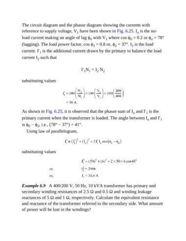
The circuit diagram and the phasor diagram showing the currents with
               reference to supply voltage, V  have been shown in Fig. 6.25. I  is the no-
                                                                                           o
                                                    1
               load current making an angle of lag ϕ  with V  where cos ϕ  = 0.2 or ϕ  = 78°
                                                                                       0
                                                                                                    o
                                                                      1
                                                            0
               (lagging). The load power factor, cos ϕ  = 0.8 or, ϕ  = 37°. I  is the load
                                                                                        2
                                                              2
                                                                             2
               current. I′  is the additional current drawn by the primary to balance the load
                           1
               current I  such that
                          2

                                                      I′ N  = I  N   2
                                                                 2
                                                        1 1
               substituting values


               As shown in Fig. 6.25, it is observed that the phasor sum of I  and I′  is the
                                                                                         o
                                                                                                 1
               primary current when the transformer is loaded. The angle between I  and I′                 1
                                                                                                  o
               is ϕ  − ϕ , i.e., (78° − 37°) = 41°.
                    0
                          2
                  Using law of parallelogram,


               substituting values


               Example 6.9   A 400/200 V, 50 Hz, 10 kVA transformer has primary and
               secondary winding resistances of 2.5 Ω and 0.5 Ω and winding leakage
               reactances of 5 Ω and 1 Ω, respectively. Calculate the equivalent resistance

               and reactance of the transformer referred to the secondary side. What amount
               of power will be lost in the windings?
   574   575   576   577   578   579   580   581   582   583   584