
Page 671 - Basic Electrical Engineering
P. 671
inserted in slots made on the rotor surface. The bars are pushed into the slots
and are connected from both sides through conducting rings. The connection
of the rotor bars with the help of end rings has been shown in Fig. 8.3 (a).
Fig. 8.3 (b) shows the three-phase stator windings connected to a three-
phase supply with the rotor closed on itself. In Fig. 8.3 (c) is shown the slip-
ring-type rotor where the rotor winding is also made in the same way as the
stator winding but the open terminals of the windings are connected
permanently to three slip rings mounted on the rotor shaft. Extra resistance
can be connected in the rotor circuit through brush and slip-ring arrangement.
The rotor along with the slip rings mounted on its shaft is free to rotate, while
brushes and the extra resistance are stationary.
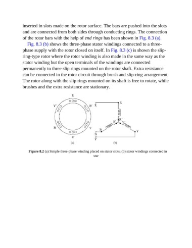
Figure 8.2 (a) Simple three-phase winding placed on stator slots; (b) stator windings connected in
star