
Page 803 - Basic Electrical Engineering
P. 803
important in any engineering and scientific activity. If we want to control a
certain quantity, e.g., the output voltage of a generator, we have to
continuously measure the output voltage because it tends to change when the
load on the generator changes. If we want to keep the output voltage constant
even when the load on the generator changes, we have to measure and send
feedback to the generator input devices to make corrections for the desired
output. Sometimes measurement has to be done from a distant place. In such
cases the measured data have to be acquired, converted to digital form,
transmitted, again converted to analog form and recorded. The input signals
received through a transducer are required to be processed, i.e., amplified or
attenuated, filtered, and converted before transmitting to the desired
destination. Signal conditioning, data acquisition, data transmission, etc., are
the important components of an instrumentation system.
Application of computers in industrial process control and monitoring has
necessitated the requirement for instruments to measure, record, and control
process variables.
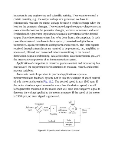
Automatic control operation in practical applications require a
measurement and feedback system. Let us take the example of speed control
of a dc motor as shown in Fig. 11.2. The desired speed is, say 1500 rpm. If
the motor develops speed somewhat more than the desired speed, a small
tachogenerator mounted on the motor shaft will send some negative signal to
decrease the voltage applied to the motor armature. If the speed of the motor
is 1500 rpm, no error signal is generated.
Figure 11.2 Speed control scheme for a dc motor