
Page 820 - Basic Electrical Engineering
P. 820
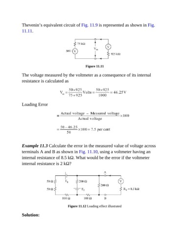
Thevenin’s equivalent circuit of Fig. 11.9 is represented as shown in Fig.
               11.11.


                                                         Figure 11.11

               The voltage measured by the voltmeter as a consequence of its internal
               resistance is calculated as


               Loading Error


               Example 11.3 Calculate the error in the measured value of voltage across

               terminals A and B as shown in Fig. 11.10, using a voltmeter having an
               internal resistance of 8.5 kΩ. What would be the error if the voltmeter
               internal resistance is 2 kΩ?


                                              Figure 11.12 Loading effect illustrated


               Solution: