
Page 34 - Fiber Optic Communications Fund
P. 34
Electromagnetics and Optics 15
Example 1.3
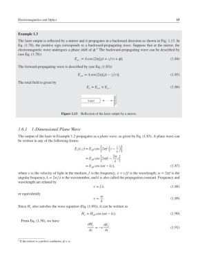
The laser output is reflected by a mirror and it propagates in a backward direction as shown in Fig. 1.13. In
Eq. (1.78), the positive sign corresponds to a backward-propagating wave. Suppose that at the mirror, the
2
electromagnetic wave undergoes a phase shift of . The backward-propagating wave can be described by
(see Eq. (1.78))
E x− = A cos [2f (t + z∕)+ ]. (1.84)
0
The forward-propagating wave is described by (see Eq. (1.83))
E = A cos [2f (t − z∕)]. (1.85)
x+ 0
The total field is given by
E = E + E . (1.86)
x x+ x−
Laser
Figure 1.13 Reflection of the laser output by a mirror.
1.6.1 1-Dimensional Plane Wave
The output of the laser in Example 1.2 propagates as a plane wave, as given by Eq. (1.83). A plane wave can
be written in any of the following forms:
[ ( z )]
E (t, z)= E cos 2f t −
x0
x
[ 2 ]
= E cos 2ft − z
x0
= E cos (t − kz), (1.87)
x0
where is the velocity of light in the medium, f is the frequency, = ∕f is the wavelength, = 2f is the
angular frequency, k = 2∕ is the wavenumber, and k is also called the propagation constant. Frequency and
wavelength are related by
= f, (1.88)
or equivalently
= . (1.89)
k
Since H also satisfies the wave equation (Eq. (1.69)), it can be written as
y
H = H cos (t − kz). (1.90)
y y0
From Eq. (1.58), we have
H
y E x
=− . (1.91)
z t
2 If the mirror is a perfect conductor, = .