
Page 32 - Instrumentation and Measurement
P. 32
For a constant flow rate (V):
Where p is differential pressure (D/P).
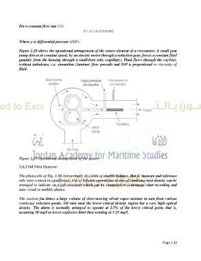
Figure 2.29 shows the operational arrangement of the sensor element of a viscometer. A small gear
pump driven at constant speed, by an electric motor through a reduction gear, forces a constant fluid
quantity from the housing through a small-bore tube (capillary). Fluid flows through the capillary
without turbulence, i.e. streamline (laminar) flow prevails and D/P is proportional to viscosity of
fluid.
Figure 2.29 Operational arrangement of the sensor
2.6.2 Oil Mist Detector
The photocells of Fig. 2.30 Are normally in a state of electric balance, that is, measure and reference
tube mist content in equilibrium. Out of balance current due to rise of crankcase mist density can be
arranged to indicate on a galvanometer which can be connected to continuous chart recording and
auto visual or audible alarms.
The suction fan draws a large volume of slow-moving oil-air vapor mixture in turn from various
crankcase selection points. Oil mist near the lower critical density region has a very high optical
density. The alarm is normally arranged to operate at 2.5% of the lower critical point, that is,
assuming 50 mg/l as lower explosive limit then warning at 1.25 mg/l.
Page | 32