
Page 70 - Instrumentation and Measurement
P. 70
5.2.3 Control Valves
Pneumatic and hydraulic systems use control valves to give direction to the flow of fluid through a
system, control its pressure and control the rate of flow. These types of valve can be termed
directional control valves, pressure control valves and flow control valves. Directional control valves,
sometimes termed finite position valves because they are either completely open or completely
closed, i.e. they are on/off devices, are used to direct fluid along one path or another. They are
equivalent to electric switches which are either on or off. Pressure control valves, often termed
pressure regulator valves, react to changes in pressure in switching a flow on or off, or varying it.
Flow control valves, sometimes termed infinite position valves, vary the rate at which a fluid passes
through a pipe and are used to regulate the flow of material in process control systems.
5.2.4 Actuators
Fluid power actuators can be classified into two groups: linear actuators which are used to move an
object or apply a force in a straight line and rotary actuators which are used to move an object in a
circular path.
The hydraulic or pneumatic cylinder is a linear actuator, the principles and form being the same for
both versions with the differences being purely a matter of size as a consequence of the higher
pressures used with hydraulics. The hydraulic/pneumatic cylinder consists of a hollow cylindrical
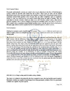
tube along which a piston can slide. Figure 5.4A shows the single acting form and Figure 5.4B the
double acting form. The single acting form has the control pressure applied to just one side of the
piston, a spring often being used to provide the opposition to the movement of the piston. The piston
can only be moved in one direction along the cylinder by the signal from the controller. The double
acting form has control pressures that can be applied to each side of the piston. When there is a
difference in pressure between the two sides the piston moves, the piston being able to move in either
direction along the cylinder. As an illustration of what is available commercially, the Parker
Pneumatics PID series have single acting or double acting cylinders in a range of bores, the standard
version being from 32 to 125 mm, and the operating pressure is a maximum of 10 bar. There is a
choice of piston material and whether it is to be cushioned at the end of its travel. Cushioning is
where the air flow out of the cylinder becomes restricted when the piston nears the end of its travel
and this slows down the movement of the piston.
FIGURE 5.4 (A) Single acting and (B) double acting cylinder.
The choice of cylinder is determined by the force required to move the load and the speed required.
Hydraulic cylinders are capable of much larger forces than pneumatic cylinders. However, pneumatic
cylinders are capable of greater speeds.
Page | 70