
Page 123 - GuardII+ Series 4208 Platform PD User Manual
P. 123
Appendix
Address Data Notes
50900 to Alert Range Phase A Pair 10 Same as User Range Phase A Pair 1 2D data
50963 2D Data
51200 to Alert Range Phase B Pair 11 Same as User Range Phase A Pair 1 2D data
51263 2D Data
51500 to Alert Range Phase C Pair 12 Same as User Range Phase A Pair 1 2D data
51563 2D Data
8.3. Monitoring PD Summary Numbers
The Qm data in the Summary Information is the most meaningful information when it
comes to trending PD data. However, simply logging the Qm number data registers is not
enough; having the Qm numbers without knowing more about the context of the measurement
could lead to misinterpreting the measurement results. To get a full picture, the Measurement
Status data register is also needed.
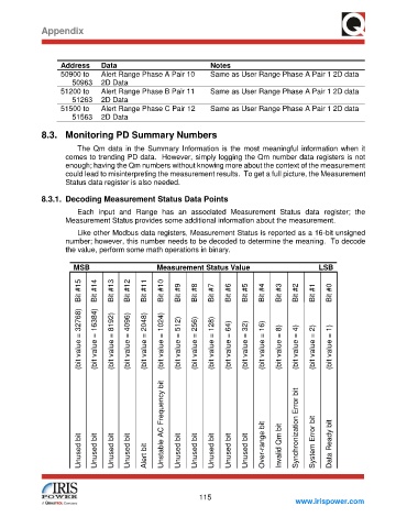
8.3.1. Decoding Measurement Status Data Points
Each input and Range has an associated Measurement Status data register; the
Measurement Status provides some additional information about the measurement.
Like other Modbus data registers, Measurement Status is reported as a 16-bit unsigned
number; however, this number needs to be decoded to determine the meaning. To decode
the value, perform some math operations in binary.
MSB Measurement Status Value LSB
Bit #15 Bit #14 Bit #13 Bit #12 Bit #11 Bit #10 Bit #9 Bit #8 Bit #7 Bit #6 Bit #5 Bit #4 Bit #3 Bit #2 Bit #1 Bit #0
(bit value = 32768) (bit value = 16384) (bit value = 8192) (bit value = 4096) (bit value = 2048) (bit value = 1024) (bit value = 512) (bit value = 256) (bit value = 128) (bit value = 64) (bit value = 32) (bit value = 16) (bit value = 8) (bit value = 4) (bit value = 2) (bit value = 1)
Unstable AC Frequency bit Synchronization Error bit
Unused bit Unused bit Unused bit Unused bit Alert bit Unused bit Unused bit Unused bit Unused bit Unused bit Over-range bit Invalid Qm bit System Error bit Data Ready bit
115
www.irispower.com