
Page 124 - GuardII+ Series 4208 Platform PD User Manual
P. 124
Appendix
Each bit shown above may or may not be set, and the total value reported in the data
register is the sum of all of the ‘bit values’ of the set bits.
As an example, suppose the value reported for Measurement Status is 1025; from the bit
values shown in the table above, 1025 = 1 + 1024. This would indicate that the “Data Ready”
and “Unstable AC Frequency” status bits are set.
Similarly, suppose the value reported for Measurement Status is 25; from the bit values
shown in the table above, 25 = 1 + 8 + 16. This would indicate that the “Data Ready”, “Invalid
Qm” and “Over-Range” status bits are set.
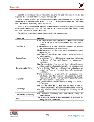
Each bit has a meaning that provides context to the measurement.
Status Bit Meaning
When the GuardII+ is first powered up, it takes up to 65 minutes
to run a full set of PD measurements and post data to
Modbus.
Data Ready The Data Ready bit is clear initially and becomes set when the
first measurement cycle is completed.
If Data Ready is not set, then there are no measurement results
completed yet.
If the System Error bit is set, then a system failure has occurred
in the monitor.
System Error Refer to Section 7 for troubleshooting instructions and contact
Iris Power LP Technical Support for assistance if
necessary.
If the Synchronization Error bit is set, then the GuardII+ cannot
detect a valid synchronization signal to run measurements.
Synchronization Error Refer to Section 7.2.4 for troubleshooting instructions and
contact Iris Power LP Technical Support for assistance if
necessary.
This bit is set when one or more of the Qm values could not be
calculated. Note that there are 4 Qm values in a GuardII+
measurement, and the Invalid Qm bit will be set if any of the
Invalid Qm
Qm values cannot be calculated.
This typically occurs when the sensitivity being used needs to
be changed.
This bit is set when the PD data from the Asset or from the
System is higher than can be read on the current sensitivity.
Over Range
This may indicate a need to change the sensitivity for this
phase.
The reference frequency was not stable during the
Unstable AC Frequency
measurement.
One of the Qm values of the measurement exceeded the
Alert
configured Alert Thresholds.
116
www.irispower.com