
Page 19 - PBL71 OI/AXM630-EN AZTEC 600 SS (WIRO)
P. 19
Aztec 600 ISE ammonia and fluoride
Single-stream ion-selective analyzers
3.5.2 General Connections
Note.
Cable entry holes are located on both sides of the enclosure.
Application board connection terminal blocks TB1 to TB8 are identified in Fig. 3.5 on page 14.
3 Installation
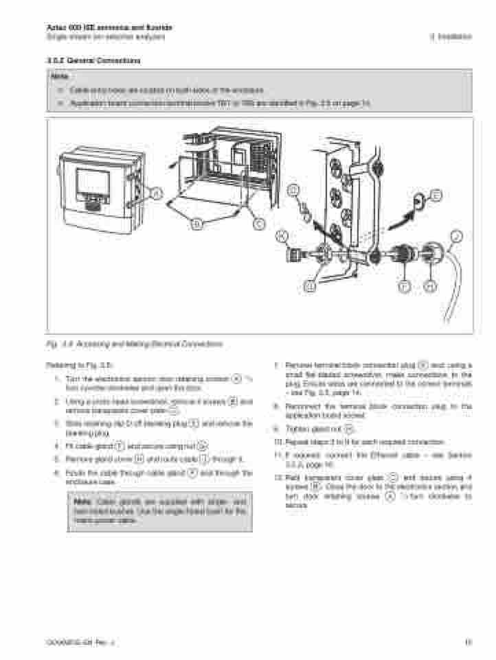
Fig. 3.6 Accessing and Making Electrical Connections
Referring to Fig. 3.6:
1. Turn the electronics section door retaining screws A 1/4 turn counter-clockwise and open the door.
2. Using a cross-head screwdriver, remove 4 screws B and remove transparent cover plate C.
3. Slide retaining clip D off blanking plug E and remove the blanking plug.
4. Fit cable gland F and secure using nut G.
5. Remove gland cover H and route cable J through it.
6. Route the cable through cable gland F and through the enclosure case.
Note. Cable glands are supplied with single- and twin-holed bushes. Use the single-holed bush for the mains power cable.
KJ
GFH
7. Remove terminal block connection plug K and, using a small flat-bladed screwdriver, make connections to the plug. Ensure wires are connected to the correct terminals – see Fig. 3.5, page 14.
8. Reconnect the terminal block connection plug to the application board socket.
9. Tighten gland nut H.
10. Repeat steps 3 to 9 for each required connection.
11.If required, connect the Ethernet cable – see Section 3.5.3, page 16.
12.Refit transparent cover plate C and secure using 4 screws B. Close the door to the electronics section and turn door retaining screws A 1/4 turn clockwise to secure.
OI/AXM630–EN Rev. J
15
A
D
E
BC
