
Page 15 - NGUYEN VAN THIEN EXPERIENCES_2013-2017
P. 15
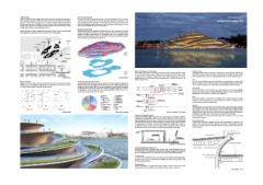
Traffic strategies External Structural System GH-5448534398
Vehicle accessible road (10m width) is kept along West border to maintain port operations, as The structural system conceptualized for the external skin involves the use of curved
well as along the quayside (5m width). In order to maximize the site efficiencies, the western reinforced concrete walls which are either bearing walls supported by foundations or by Sustainability/Feasibility 04
vehicular traffic route is also utilized for the museum, including collection and general internal columns which line up with the external steps of the "terraces". In some locations the
deliveries, taxi access and VIP/disabled car access. Along this road, art loading dock, general deep external walls act as transfer elements over some of the larger exhibition spaces in order
loading dock, drop-off area and parking are located under the eaves of the building. Limited to improve the flexibility of the internal function spaces.
at night, kitchen delivery is done through the forecourt.
Internal Structural System
Public pedestrian circulation is organized on the quayside, around Center Court and through The floor support system is a combination of bearing reinforced concrete walls and discrete feature
the passageways, so the pedestrian and car circulation are clearly separated. columns. Shear walls are used where necessary to support the floors and also provide lateral
stability to the building. Blockwork walls can be utilized where it is more economical. The floor
system is envisaged to comprise of either a beam and slab arrangement or post-tensioned system
in order to achieve some of the longer span floor areas.
SITE
hall entrance port entrance
turning point
hall delivery
cafe delivery
PORT
cafe entrance
HALL LAIVASILLANKATU
CAFE SERVICE artwork delivery
ONLY NIGHT MUSEUM
general delivery
drop-off area
OLD MARKET museum entrance
ETELÄRANTA
PALACE HOTEL
High Level Schematic of HVAC system Wooden Facade
0 10 20 50 100m
N The cooling and heating of the building will be done using the conditioned water system Finish-grown Siberian larch wood will be utilized for the external cladding. The wooden
connected to district heating and cooling network through plate heat exchangers. The facade will be optimized using computational methods based on detailed structural analysis
conditioned water will be used to supply the Pre heat, cooling and heating coil in the air of bearing walls and then constructed using digital fabrication to archive desirable accuracy.
Traffic strategies Structural analysis handling units, the trench heating and snow melting system, as well as hot water for the
kitchens and bathrooms. Roof
Museum flexibility Construction cost and Project timeline Roof deck is paved with stone on layers of insulation and waterproofing. Around the roof
Because of various vertical connections and multiple sub entrances from the terraces, the Comparing with similar sized contemporary museums, the allowance budget for Guggenheim HEATING COIL edge, stone slabs are replaced with grass stripes to create enjoyable green space for the public.
exhibition space can be flexibly arranged in a loop or two loops on the two floors, as well as Museum Helsinki is relatively higher, therefore innovative structure, high quality finishes and ENTHALPY WHEEL ADIABATIC HUMIDIFIERS The curved wall overhangs create covered spaces underneath where people can hang out.
COOLING COIL
up to eight separated galleries with independent entrances. equipment as well as advanced MEP system can be attainable. Roughly estimated, foundation EXTRACT FAN
and structure will account for one third of the construction budget, cladding and roofing for EXHAUST AIR RETURN AIR Internal wall
15-20%, finishes 10-15% and MEP 25%. The overall design period is expected to be 15 - 18 FRESH AIR -- CONDITIONED Neutral white walls are chosen for galleries, to create a background of art works and highlight
3F 3F 3F SUPPLY AIR
months and the construction period 36 months. SUPPLY FAN dynamic curved spaces. Service accessible wall (200mm depth), composed of double layered
PREHEAT COIL FILTRATION
Stairs / EV HEATING WATER TO gypsum boards, has a slit near the ceiling to extract warmed air.
TRENCH HEATING
DISTRICT
EV slope EV / slope EV / slope HEATING SUPPLY
Foundations Function Equipment &
9% Specialities 3.5% Floor
Vertical Structure Stairs & Vertical
2F 2F 2F 10% Transportation 2% HEATING WATER PUMP Raised floor in galleries contains ducts for Displacement Ventilation System in its depth
Floor & Roof Structure Plumbing Systems & HEATING WATER FOR (450mm) as well as trench heaters near large glazing. The finishes are polished precast
13% Fire Protection 2.5% RETURN WATER FROM SNOW MELTING SYSTEM concrete panels and wood flooring alternately.
DISTRICT NETWORK
Exterior Cladding Heating, Ventilation &
13.5% Air Conditining 11%
Roofing & Waterproofing Electrical HEATING WATER PUMP
1F 1F 1F 6% 8% Lighting
Multi Multi Multi DISTRICT
Interior Partitions, General Conditions COOLING SUPPLY Natural lighting is carefully introduced into the gallery spaces from linear skylights. Skylights
Doors & Glazing 4.5% 6%
Floor, Wall & Overhead are composed of three layers of glass panels. The intermediate layer is highly insulated
Single Stroke Twin loops Multiple access Ceiling Finishes 8.5% 2.5%
PLATE HEAT COOLING WATER PUMP double glazing. External and internal translucent panels are used mainly for lighting control.
Exhibition plans Construction cost analysis EXCHANGER High Level Schematic of HVAC system Mortised louvers are placed between the layers and used to regularly adjust the transmittance
of daylight into the gallery space to provide a near constant level of natural light.
Displacement Ventilation System For artificial lighting, color-accurate LED lights will be applied to reduce cooling
Displacement Ventilation System is applied to create a high-quality indoor setting for exhibitions. requirements in summer.
By supplying air through grills on floors, the system frees top lit spaces of ducts and outlets and
walls of supply grills. The system forms a ‘cool puddle’ on the floor which will naturally spread Snow melting system
towards heat sources and begin to rise due to buoyancy. Air velocities remain very low throughout A water based snow and ice melting system for the roof/walkway is included in the
so the gallery space will be quiet. In times of low occupancy, the displacement air can be re- design. As the temperature of water required for this system is not very high, returning
circulated with minimum fresh air input. The reduced airflow requirements and lower velocities water from the district network along with plate heat exchangers will be used to produce
also mean lower system pressure and hence reduced energy consumption from the fans. the heating water.
Return air can be
up to 30ºC.
Heat gains from people and
lights drive buoyancy forces.
Perimeter heating for
winter comfort and to offset
Cold air cold downdrafts from windows.
less than 18ºC.
Displacement Ventilation System
Air Handling Units and Heat Recovery
Fresh air and displacement ventilation air will be provided using a central air handling unit (AHU);
AHU will include a LTHW preheat coil for frost protection, heating and cooling coil for conditioning
the air, an enthalpy wheel for heat and moisture recovery and bag and panel filters for filtration.
Trench heating
In addition to the displacement system, trench heating will be applied under large glazing to
keep them warm and prevent downdrafts. The LTHW for this system will be produced using
the district heating network.
Humidification
Adiabatic humidifiers are applied for this project, which "atomize" water into very small
droplets which remain in suspension until evaporate into the air stream in the AHU.
Section detail S = 1/50