
Page 349 - statbility for masters and mates
P. 349
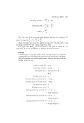
Bending moment   wX  l   X  2
Bending of beams 337
MaximumBM wl l l 42
; BMmax   wl2 8
Also, the area of the shearing force diagram between the ordinate AC 1 l wl wl2
andOisequalto2 2  2 or 8 .
These principles can now be applied to ®nd the shearing forces and bending moments for any simply supported beam.
Note again how BMmax occurs at point `O', the point at which SF   0. This must be so for equilibrium or balance of forces to exist.
Example
A uniform beam is 16 m long and has a mass of 10 kg per metre run. The beam is supported on two knife edges, each positioned 3 m from the end of the beam. Sketch the shearing force and bending moment diagrams and state where the bending moment is zero.
Mass per metre run Total Mass of beam The Reaction at C
The Shear force at A The Shear force at L.H. side of B The Shear force at R.H. side of B The Shear force at O Bending moment at A Bending moment at 1 m from A
Bending moment at 2 m from A Bending moment at 3 m from A
  10 kg
  160 kg
  The Reaction at B   80 kg
  O
   30 kg
   50 kg
  O
  O
  1   10   12
  5 kg m (negative)   2   10   1
  20 kg m (negative)   3   10   1 12
  45 kg m (negative)
