
Page 347 - statbility for masters and mates
P. 347
Bending of beams 335
and a force W downwards appears. This must be considered in addition to the force W/2 upwards at A. The resultant is a shearing force of W/2 downwards and this force is then constant from O to B as shown in Figure 40.11 by the straight line EF.
The bending moment diagram can now be drawn in the same way or by ®rst calculating the area under the shearing force diagram between the ordinate AC and various points along the beam and then plotting these values as ordinates on the bending moment diagram. It will be seen that the bending moment is zero at the ends and attains its maximum value at the mid-point in the beam indicated by the ordinate OG. Note BMmax occurs when SF 0.
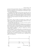
Case II
Now consider a beam of constant cross-sectional area, of length l, and weight w per unit length. Let the beam be simply supported at its ends as shown in Figure 40.12, at reactions RA and RB.
The total weight of the beam is wl. The reaction at each end is equal to wl=2, half of the weight of the beam.
The shearing force and bending moment diagrams can now be drawn as in the previous example. In Figure 40.12, let AB represent the length of the beam (l) drawn to scale. At A the shearing force is wl=2 upwards and this is shown on the graph by the ordinate AC. Because the weight of the beam is evenly distributed throughout its length, the shearing force decreases uniformly from A towards B.
At the mid-point (O) of the beam there is a shearing force of wl=2 downwards (half the weight of the beam) and one of wl=2 upwards (the reaction at A) to consider. The resultant shearing force at O is therefore zero. Finally, at B, there is a shearing force of wl downwards (the weight of the beam) and wl=2 upwards (the reaction at A) to consider, giving a resultant shearing force of wl=2 downwards which is represented on the graph by the ordinate BD.
Fig. 40.12
