
Page 346 - statbility for masters and mates
P. 346
334 Ship Stability for Masters and Mates
Fig. 40.10
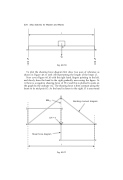
To plot the shearing force diagram ®rst draw two axes of reference as shown in Figure 40.11 with AB representing the length of the beam (l).
Now cover Figure 40.10 with the right hand, ®ngers pointing to the left, and slowly draw the hand to the right gradually uncovering the ®gure. At A there is a negative shearing force of W/2 and this is plotted to scale on the graph by the ordinate AC. The shearing force is then constant along the beam to its mid-point O. As the hand is drawn to the right, O is uncovered
Fig. 40.11
