
Page 138 - ro membanes
P. 138
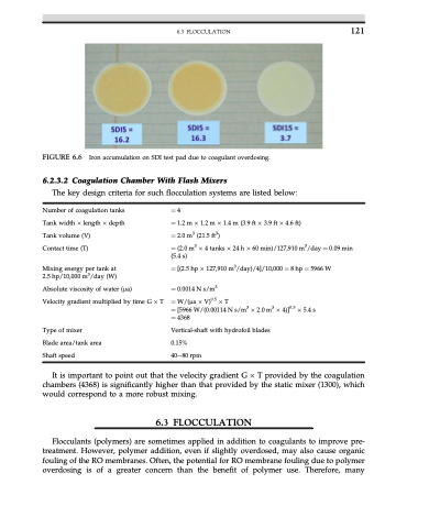
  FIGURE 6.6 Iron accumulation on SDI test pad due to coagulant overdosing.
6.2.3.2 Coagulation Chamber With Flash Mixers
The key design criteria for such flocculation systems are listed below:
6.3 FLOCCULATION 121
  Number of coagulation tanks Tank width  length  depth Tank volume (V)
Contact time (T)
Mixing energy per tank at 2.5 hp/10,000 m3/day (W)
Absolute viscosity of water (ma)
Velocity gradient multiplied by time G  T
Type of mixer
Blade area/tank area Shaft speed
1⁄44
1⁄41.2m1.2m1.4m (3.9ft3.9ft4.6ft)
1⁄4 2.0 m3 (21.5 ft3)
1⁄4 (2.0 m3  4 tanks  24 h  60 min)/127,910 m3/day 1⁄4 0.09 min (5.4 s)
1⁄4 [(2.5 hp  127,910 m3/day)/4]/10,000 1⁄4 8 hp 1⁄4 5966 W 1⁄4 0.0014 N s/m3
1⁄4 W/(ma  V)0.5  T
1⁄4 [5966 W/(0.00114 N s/m3  2.0 m3  4)]0.5  5.4 s 1⁄4 4368
Vertical-shaft with hydrofoil blades 0.15%
40e80 rpm
 It is important to point out that the velocity gradient G  T provided by the coagulation chambers (4368) is significantly higher than that provided by the static mixer (1300), which would correspond to a more robust mixing.
6.3 FLOCCULATION
Flocculants (polymers) are sometimes applied in addition to coagulants to improve pre- treatment. However, polymer addition, even if slightly overdosed, may also cause organic fouling of the RO membranes. Often, the potential for RO membrane fouling due to polymer overdosing is of a greater concern than the benefit of polymer use. Therefore, many
