
Page 26 - ro membanes
P. 26
1.2 MEMBRANE-FOULING MECHANISMS 9
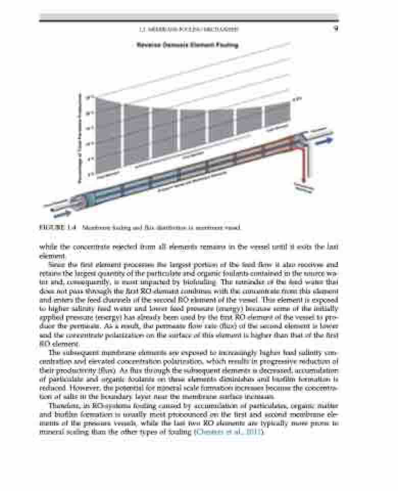
FIGURE 1.4 Membrane fouling and flux distribution in membrane vessel.
while the concentrate rejected from all elements remains in the vessel until it exits the last element.
Since the first element processes the largest portion of the feed flow it also receives and retains the largest quantity of the particulate and organic foulants contained in the source wa- ter and, consequently, is most impacted by biofouling. The reminder of the feed water that does not pass through the first RO element combines with the concentrate from this element and enters the feed channels of the second RO element of the vessel. This element is exposed to higher salinity feed water and lower feed pressure (energy) because some of the initially applied pressure (energy) has already been used by the first RO element of the vessel to pro- duce the permeate. As a result, the permeate flow rate (flux) of the second element is lower and the concentrate polarization on the surface of this element is higher than that of the first RO element.
The subsequent membrane elements are exposed to increasingly higher feed salinity con- centration and elevated concentration polarization, which results in progressive reduction of their productivity (flux). As flux through the subsequent elements is decreased, accumulation of particulate and organic foulants on these elements diminishes and biofilm formation is reduced. However, the potential for mineral scale formation increases because the concentra- tion of salts in the boundary layer near the membrane surface increases.
Therefore, in RO-systems fouling caused by accumulation of particulates, organic matter and biofilm formation is usually most pronounced on the first and second membrane ele- ments of the pressure vessels, while the last two RO elements are typically more prone to mineral scaling than the other types of fouling (Chesters et al., 2011).
