
Page 238 - TORO PRODUCT CATALOGUE NOV_2019
P. 238
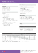
 P220 Scrubber Series cont.
  Specifications
Dimensions
Additional features
 • 25 mm: 171 x 92 mm H x W
• 40 mm: 184 x 92 mm H x W
• 50 mm: 241 x 156 mm H x W
• 80 mm: 273 x 156 mm H x W
Operating Specifications
• FlowRange:
• 25 mm: 20-151 Lpm
• 40 mm: 114-416 Lpm
• 50 mm: 303-568 Lpm
• 80 mm: 493-1137 Lpm
• OperatingPressure
• 25 mm and 40 mm Models: 70-1500 kPa
• 50 mm and 80 mm Models: 140-1500 kPa
• Minimumpressuredifferential(betweeninletandoutlet)for pressure regulation: 70 kPa
• Bodystyles:
• Globe/Angle:25,40,50and80mmfemalethreads
• 588403 Solenoid: 24 VAC (50) Standard
• Inrush: 50 Hz: 0.40 amps
• Holding: 50 Hz: 0.2 amps
• Tough glass-filled nylon and stainless steel construction
• Internal and External bleed
• Standard,built-inSchrader-typevalvefordownstream pressure verification
• Flow control independent of solenoid
• Self-aligning bonnet to ensure correct installation
• Self-cleaning,stainlesssteelmeteringrod
• Low-flowcapabilitydownto20LpmwithEZReg
• 316nuclear-gradestainless-steelfilterformaximum corrosion resistance
Options Available
• EZR-30 - EZReg, 30-200 kPa Regulator Module
• EZR-100 - EZReg, 30-700 kPa Regulator Module
• 588403:24VACSolenoidAssembly,50Hz,CaptivePlunger
• DCLS-P - Potted DC Latching Solenoid Assembly (max. pressure 820 kPa)
• SGS -12 - Spike GuardTM Solenoid: 50/60 Hz (24 VAC)
Warranty
• Fiveyears
 P-220 Scrubber Series Model List
 Model
  Description
  P220S-23-54 P220S-23-56 P220S-23-58 P220S-23-50
 P220S, 25 mm BSP with ACTTM System P220S, 40 mm BSP with ACTTM System P220S, 50 mm BSP with ACTTM System P220S, 80 mm BSP with ACTTM System
      P-220 Scrubber Series Friction Loss Data – kPa
 Size
 Configuration
     Flow Rate Lpm
 20
  35
  50
  60
  75
  80
  100
  120
  150
  200
  250
  300
  350
  400
  450
  500
  550
  600
  700
  800
  900
  1000
  1100
  25 mm
 Globe Angle
  32 29
33 32
  28 27
24 22
  21 18
22 18
  32 29
 47 42
73 64
                 40 mm
 Globe Angle
      8 7
 9 9
 12 11
 20 16
 34 28
 52 43
 78 64
 102 86
 131 111
          50 mm
 Globe Angle
            25 19
 33 26
 42 35
 56 43
 64 53
 76 63
       80 mm
 Globe Angle
                        15 13
  18 16
 21 19
 28 24
  37 32
 46 40
  56 50
 67 61
   Flow rates are recommended not to exceed 35 kPa loss.
Note: For optimum performance when designing a system, be sure to calculate total friction loss to ensure sufficient downstream pressure. For optimum regulation performance, size regulating valves toward the higher flow ranges.
 Company policy is one of constant improvement and therefore changes in specifications may be made without notice and without incurring liability. Please refer to www.toro.com.au
Toro Australia Pty Ltd, 53 Howards Road, Beverley, South Australia, 5009.
Phone 1300 130 898, fax (08) 8243 2488. A.B.N. 47 001 310 443
 222
