
Page 146 - eProceeding - IRSTC & RESPEX 2017
P. 146
Haryani / JOJAPS – JOURNAL ONLINE JARINGAN COT POLIPD
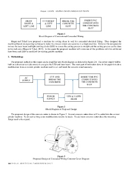
DRAW CUT RIGHT BREAK THE INSERT PVC
RIGHT & & LEFT CONCRETE CONDUIT INTO
LEFT LINE LINE SLOT THE CONCRETE
SLOT
Figure 1
Block Diagram of Conventional Concealed Wiring
Magar and Trikal have proposed a machine for cutting chase in wall for concealed electrical fitting. They designed the
machined based on engraving technique to make the process simple and accurate in a single machine. However the designed did
not use the laser beam and light emitting diode (LED) to ensure the cutting process is straight and the cutting process can be done
in the dark area (Magar & Trikal, 2015). In this paper the proposed machine will overcome all the problems with the additional
laser beam and LED by modified the existing grinder machine.
2. Methodology
The proposed method on this paper can be simplified into block diagram as depicted in Figure 2.0. The power supply will be
built as a direct current (dc) source to energize the LED and laser beam. The main part of innovation done in this paper is to do a
modification from an existed grinder machine used to cut and break the concrete simultaneously.
CUT AND INSERT THE PVC
AC
SUPPLY BREAK THE CONDUIT INTO
CONCRETE THE CONCRETE
SLOT
POWER LED & LASER
SUPPLY BEAM
Figure 2
Block Diagram of Proposed Design
The proposed design of the concrete cutter is shown in Figure 3. Several concrete cutter discs will be added into the existed
grinder machine. To do such a thing some modifications need to be made. To add more concrete cutter discs the mounting
flange need to be expand.
Figure 3
Proposed Design of Concealed Wiring Concrete Cutter Diagram
144 | V O L 8 - I R S T C 2 0 1 7 & R E S P E X 2 0 1 7