
Page 147 - eProceeding - IRSTC & RESPEX 2017
P. 147
Haryani / JOJAPS – JOURNAL ONLINE JARINGAN COT POLIPD
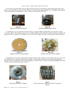
A new shape of mounting flange which is longer then the existed one will be designed. The mounting flange design with a
pocket on it to insert the key used to avoid the concrete cutter discs moving during the wiring work. An original mounting flange
and a new designed of mounting flange is shown in Figure 4a and Figure 4b respectively.
Figure 4a Figure 4b
Original Mounting Flange Diagram Modified Mounting Flange Diagram
A modification of concrete cutter disc need to be made to ensure the modified mounting flange can hold all the concrete
cutter discs perfectly. The original concrete cutter disc and the modified concrete cutter disc is shown in Figure 5a and Figure 5b
respectively. The arrangement of the concrete cutter discs with a disc washers inserted to mounting flange is shown in Figure 6.
Figure 5a Figure 5b
Original Concrete Cutter Disc Diagram Modified Concrete Cutter Disc Diagram
The modification of a steel flat washer is shown in Figure 6 and the final arrangement of the concrete cutter discs with a steel
flat washers inserted to mounting flange is shown in Figure 7. Based on the observation by the author the suitable distance
between each concrete cutter disc is 0.2cm which separated by a steel flat washer, to ensure the cutting and drilling process of the
wall run smoothly without damaging the wall itself.
Figure 6 Figure 7
Modified Steel Flat Washer Diagram Concrete Cutter Discs and Steel Flat Washers Arrangement
Diagram
145 | V O L 8 - I R S T C 2 0 1 7 & R E S P E X 2 0 1 7