
Page 336 - PUC 2017 Master Catalog
P. 336
TECHNICAL INFORMATION
Wherever there is a conductor carrying electric current, it is Welding Connectors
necessary to make a connection. This is true whether the con- Welding, particularly of aluminum bus, has become increasing-
ductor is a solid or stranded wire, a rectangular bus bar or a ly popular because the materials are united in a homogeneous
piece of copper pipe. This is also true whether the conductor bond. The bus can be joined directly or through the use of weld-
is an inch in length, a foot in length, or several hundred feet in ments. Weldments eliminate the need for field cutting and match-
length. Conductors are joined by several methods. The oldest ing. They also act as fixtures and help align the bus structure
methods are the fusion of conductors by means of soldering, during erection. Tungsten inert gas (TIG) has become increasingly
brazing or welding, with the very oldest being the blacksmith popular for joining of aluminum conductors.
form of welding. Joining techniques of this type require special
skill and special equipment, consequently, other means have
been developed which are more generally applied. These are Pressure Connectors - Bolted and Compression
the pressure methods which are divided between the bolted The simplest and most widely used method of joining conductors
or mechanical type joint and the compression type connec- is by means of externally applied pressure. This pressure can be
tor which uses special tools to develop the necessary forces. developed by means of clamp type connectors using bolts and
One other joining technique that is frequently used is soldering. nuts or by compression connectors using special compression
However, this has its limitations, because of the possibility of tools to develop the necessary forces.
the joints melting out during temporary overload conditions.
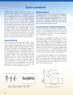
As two surfaces are brought together to make a joint, the micro-
Connector Materials scopic peaks touch each other as shown in Figure 1. As force
continues to be applied, the relatively few peaks flatten out into
Since most electrical conductors are either copper or alumi- a large number of plateaus and current is transferred across the
num, it also has become standard of the connector industry interface. The relationship is clearly shown in Figure 2 in which
to make connectors of copper and aluminum. The category of resistance is plotted against force. The important thing about this
copper connectors includes pure copper and alloys of bronze relationship is that once sufficient force has been applied to estab-
and brasses. The materials can be fabricated by casting, forg- lish a safe value of resistance, considerable relaxation can occur
ing, extruding, punching, or any combination of these process- before the resistance starts to rise again. A well designed clamp
es. The aluminum connectors are made of alloys used to pro- or compression connector thus has some safety factor built into it.
vide the best electrical conductivity. However, in some cases,
a compromise material is used to give optimum combination All clamp type connectors depend upon the thrust developed by
of electrical conductivity and mechanical strength. A general the bolts to deliver the force necessary for a sound, stable con-
practice has been to use copper connectors for copper con- nection. For a bolt to do its job, it must have adequate strength so
ductor and aluminum connectors for aluminum conductor. that it can be torqued properly, it must develop correct thrust for
In some cases where a transition from copper to aluminum con- the installation torque recommended, and above all, it must be
ductors must be made, it is advantageous to use a bi-metallic reliable and not fail during service.
connector, thus making the transition in the connector rather
than in the junction of the connector and conductor.
A Tightening
B Relaxing
e
c
t n
c a t
a s
t i F2 R1 F1
n s
o e
C R
Contact Force
Figure 1. As force is increased, the surface roughness
flattens out creating a multiplicity of parallel paths Figure 2. Contact resistance curves
316 317