
Page 18 - Biogas Plant Construction
P. 18
360 Biogas
6.2 Gas processing unit
Chandrasekar (2006) demonstrated the gas processing unit (GPU). In stage one biogas from
the digester will be cleaned of moisture droplets, particulates and hydrogen sulfide. The
cleaned gas mixture, which consists primarily of methane (CH 4) and carbon dioxide (CO 2),
will be then converted in stage 2 to ultra-high purity hydrogen in a steam reformer. As a
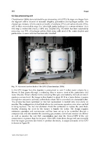
first step to realize this vision, a GPU was installed (Fig. 19) which has been successfully
removing over 99% of hydrogen sulfide (H 2S) along with most of the water droplets and
particulates. A steam reformer has been also installed.
Fig. 19. Activated carbon beds of the GPU (Chandrasekar, 2006)
In the GPU biogas from the digester is pressurized to over 3 inches water column by a
blower. It then passes through a coalescing filter to remove most of the particulates and
water droplets. Water collected in the coalescing filter gets automatically drained out once it
reaches a certain level. The biogas is then heated to about 85 o F in a heater before it passes
through two successive activated carbon beds where H 2S is converted into elemental sulfur.
The process has been optimized so that bed replacement is needed only once every six
months. The configuration of dual beds allows for continuous operation even when one bed
is being replaced. The bed manufacturer should be contracted to replace the used beds,
thereby obviating the need for the farmer to handle the sulfur. The design requires
minimum operation and maintenance and has been set up to be controlled through a
computer that will also monitor the incoming gas pressure, control and monitor the blower
as well as monitor the exit H 2S concentration and shut the blower/GPU if the exit
concentration is greater than the set point. If the GPU shuts down, biogas will automatically
feed the engine generator like before to produce electricity. A simple schematic of the GPU
is shown in Figure 20.
www.intechopen.com