
Page 717 - SUBSEC October 2017_Neat
P. 717
- 13 -
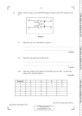
(e) Figure 3 shows a logic circuit with TWO inputs, R and S, and TWO outputs Q and
Q’.
DO NOT WRITE IN THIS AREA
Figure 3
(i) Name the type of circuit shown in Figure 3.
...........................................................................................................................
...........................................................................................................................
[1 mark] DO NOT WRITE IN THIS AREA
(ii) Name the logic gate used in the circuit.
...........................................................................................................................
...........................................................................................................................
[1 mark]
(iii) Copy and complete the sequential truth table given in Table 1 to show the
action of the circuit in Figure 3.
[2 marks]
Sequence I 1 I 2 X Y
1 0 1 1 0
2 0 0 1 0
3 1 0 DO NOT WRITE IN THIS AREA
4 0 0
5 0 1
6 0 0
GO ON TO THE NEXT PAGE
02238020/CAPE/SPEC 2017
‘‘*’’Barcode Area”*”
Sequential Bar Code