Page 19 - Basics of Electrical, Electronic and Communication
P. 19

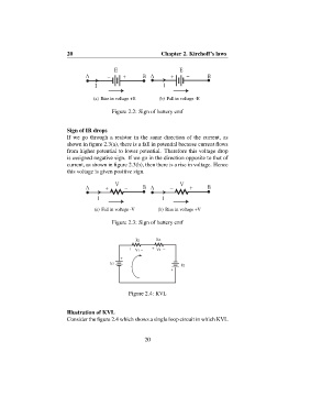
20                                 Chapter 2. Kirchoff’s laws


                                             Ε                       Ε
                                  Α       −     +       Β  Α         +     −    Β
                                      Ι                        Ι


                                     (a) Rise in voltage +E   (b) Fall in voltage -E

                                            Figure 2.2: Sign of battery emf


                           Sign of IR drops
                           If we go through a resistor in the same direction of the current, as
                           shown in figure 2.3(a), there is a fall in potential because current flows
                           from higher potential to lower potential. Therefore this voltage drop
                           is assigned negative sign. If we go in the direction opposite to that of
                           current, as shown in figure 2.3(b), then there is a rise in voltage. Hence
                           this voltage is given positive sign.

                                              V                       V
                                  Α       +      −      Β  Α      −       +     Β
                                       I                        I

                                     (a) Fall in voltage -V  (b) Rise in voltage +V

                                            Figure 2.3: Sign of battery emf


                                                     R1      R2
                                                       _   +   _
                                                  + V1       V2
                                               +                   _
                                           E1
                                               _                      E2
                                                                  +


                                                  Figure 2.4: KVL


                           Illustration of KVL
                           Consider the figure 2.4 which shows a single loop circuit in which KVL


                                                        20
   14   15   16   17   18   19   20   21   22   23   24