
Page 390 - Med Plaza and Cancer Center
P. 390
Microprocessor Digital Manifold
USER RESPONSIBILITY
The information contained in this Installation and Maintenance Manual, pertains only to the ALERT-2
microprocessor based digital manifold. This product will perform in conformity with the descriptions
contained in this manual when assembled, operated, maintained and serviced in accordance with the
Corporation
Corporation
installation instructions provided. the right connection
The manifold must be checked periodically. Parts that are broken, missing, worn, distorted or
contaminated, must be replaced immediately. Should such repair or replacement become necessary,
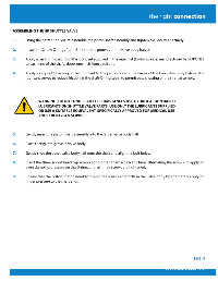
ASSEMBLING THE HP SHUTTLE VALVE
please contact Amico Corporation or their distributors.
Installing CO2 and N2O manifolds outdoors. Please refer to NFPA Code: 5.1.3.3.1.8 Central
1. Using the parts supplied, re-assemble the piston shaft assembly and tighten the lock nut securely.
supply systems for nitrous oxide and carbon dioxide shall be prevented from reaching
temperatures lower than the recommendations of the central supply system’s manufacturer,
2. Install the 2 new O-rings (item #11) into the grooves in the valve body halves.
but shall never be lower than -7°C (20°F) or greater than 54°C (130°F).
3. Apply a very light coating of the lubricant supplied in the repair kit (Krytox Grease, manufactured by DUPONT),
All Manifolds should not be repaired or altered without prior written approval by Amico
to each end of the shaft, about one inch from each end.
Corporation or it’s distributors. Failure to comply will void all warranty on the manifold.
Statements in this manual preceded by the words WARNING, CAUTION, DANGER and NOTE are of
4. Apply a very light coating of the lubricant to the piston bore of the larger of the two valve body halves. This
lubricant serves to reduce friction at the shaft O-ring seals, to permit easy shutting of the shaft assembly.
special significance. Please read these sections carefully.
WARNING: DO NOT UNDER ANY CIRCUMSTANCES USE HYDROCARBON BASED
LUBRICANTS ON SHUTTLE VALVE PARTS. USE ONLY THE LUBRICANTS SUPPLIED
WARNING: denotes steps which can prevent injury.
OR USE A SUITABLE EQUIVALENT, SPECIFICALLY APPROVED FOR MEDICAL USE
AND FOR OXYGEN SERVICE.
5. Gently insert the piston shaft assembly into the larger valve body half.
CAUTION: denotes steps which can prevent damage to equipment.
6. Place O-ring into grove in valve body.
7. Gently slide the other valve body half onto the shaft and align the bolt holes.
8. Insert the three socket head cap screws and tighten them a turn at a time, alternating the screws, to apply an
even clamping pressure on the O-ring, until all three screws are tightened.
DANGER: denotes steps which can prevent electrical shock to equipment or to
prevent serious injury and/or death.
9. Ensure that the piston shaft assembly moves freely back and forth in the valve body by alternately applying
finger pressure to the shaft ends.
Page: 4
PAGE 37
www.amico.com