
Page 521 - Med Plaza and Cancer Center
P. 521
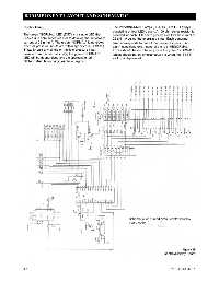
8/COMPONENT LAYOUT AND SCHEMATIC


              Display Lamps                                     The red “ABNORMAL” lamps (DS1-DS6) are LED arrays
                                                                consisting of four LED’s each. A 150 ohm series resistor is
              The green “NORMAL” LED (DS7) is a single LED that  provided for each LED bar to provide a dc forward current of
              uses a 390 ohm series resistor to develop the dc forward  22 ± 4 mA during the energized state. Each abnormal
              current of 22 ± 4 mA. The green “NORMAL” lamp glows  lamp corresponds to one of the pressure inputs. If no
              when all pressure inputs are within specified (NORMAL)  alarm conditions exist, none of the red “ABNORMAL”
              limits. Should any single or multiple pressure input  LED’s should be on. The only time the green “NORMAL”
              deviate from the normal limit(s) the green “NORMAL”  lamps should be on simultaneously is when the “TEST”
              LED will be deenergized and the appropriate red   switch is depressed.
              “ABNORMAL” lamp bar(s) will be energized.


                                                                         Schematic for printed circuit control/display
                                                                         board code
                                                                                   1      2


                                                                                                       Figure 29
                                                                                             Control/Display Board


              8-2                                                                              0178-0135-000  Rev. A