
Page 516 - Med Plaza and Cancer Center
P. 516
6/REPAIR PROCEDURE
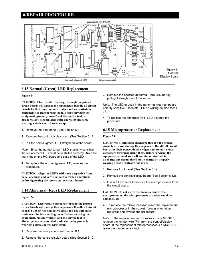
Figure 24
Control/
Display Board
6.13 Normal (Green) LED Replacement
Figure 24 3. Remove the affected abnormal (red) LED bar by
pulling it straight out of the socket.
CAUTION: Electrostatic discharge through the printed
circuit boards will damage the components. Handle all circuit Note: The LED(s) used in the abnormal (red) lamps are
polarity sensitive. Orientate LED so writing on side faces
boards by their nonconductive edges and use anti-static
J1.
containers for transporting them. Before servicing the
equipment, ground yourself and the service tool to 4. To replace the abnormal (red) LED, reverse the
discharge any accumulated static charge by properly
procedure.
wearing a static control wrist strap.
1. Remove the front panel (See Section 6 1). 6.15 Microprocessor Replacement
2. Remove the control/display board (See Section 6.12). Figure 24
3. Pull the normal (green) LED straight out of the socket. CAUTION: Electrostatic discharge through the printed
circuit boards will damage the components. Handle all circuit
Note: Since the normal (green) LED is polarity sensitive, boards by their nonconductive edges and use anti-static
the replacement LED must be in stalled correctly. Note the containers for transporting them. Before servicing the
markings on the P.C. board and base of the LED. equipment, ground yourself and the service tool to
discharge any accumulated static charge by properly
4. To replace the normal (green) LED, reverse the wearing a static control wrist strap.
procedure.
1. Remove front panel (See Section 6.1).
CAUTION: Align the LED’s with their respective front
2. Remove the control/display board (See Section 6.12).
panel openings and verify respective switch operations
before tightening the screws on the circuit board.
3. Use a IC extractor to remove the microprocessor from
the circuit board.
6.14 Abnormal (Red) LED Replacement
CAUTION: Do not use excess force to remove the
microprocessor; the microprocessor or socket could be
Figure 24
damaged, etc.
CAUTION: Electrostatic discharge through the printed
4. To replace the microprocessor, insert the replacement
circuit boards will damage the components. Handle all circuit
microprocessor in the socket (proper orientation
boards by their nonconductive edges and use anti-static required) and reverse the procedure.
containers for transporting them. Before servicing the
equipment, ground yourself and the service tool to Note: If the replacement microprocessor is a MC6805,
discharge any accumulated static charge by properly remove the jumper wire (P1) from the control/display
wearing a static control wrist strap. board. If the replacement microprocessor is a MC68705,
leave the jumper wire intact.
1. Remove the front panel (See Section 6.1).
2. Remove the control/display board (See Section 6.12).
0178-0135-000 Rev. A 6-6