
Page 513 - Med Plaza and Cancer Center
P. 513
6/REPAIR PROCEDURE
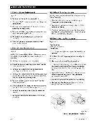
6.3 Audio Alarm Replacement 6.5 Teflon® Tape Application
Figure 21 Use this procedure when Teflon® tape is applied to any
fitting. Figure 22.
1. Remove the front panel (see Section 6.1).
1. Wrap tape clockwise, starting one thread up, as
2. Disconnect the 2 pin audio connector from the power viewed from end of male fitting.
supply board.
2. Apply enough pressure so tape just starts to follow
3. Remove the 2 screws that hold the audio mounting contours of threads.
bracket to the rough-in box.
3. The tape must be wrapped around the fitting twice.
4. Remove the Phillips head screw and spacer from the Perform the Leak Test Procedure (Section 4.4) on all
back of the mounting bracket. fittings that were disconnected.
5. To reinstall the replacement alarm, reverse this
procedure. 6.6 Hose Coupling Replacement
6. After the front panel has been reinstalled, system Figure 21
power can be reapplied.
Tools Required:
9/16" open end wrench
6.4 Transformer Replacement Teflon® tape
Figure 21 1. Turn off gas supply to the coupling that needs to be
replaced.
WARNING: Electrical Shock Hazard. Disconnect system
power before beginning the transformer replacement WARNING: Turn off the gas supply before starting this
procedure. procedure.
1. Remove the front panel (See Section 6.1). 2. Remove the front panel (See Section 6.1).
2. Disconnect the 2 pin audio alarm connector from the 3. To disconnect the coupling, use a 9/16" wrench to turn
power supply board. the coupling counterclockwise. Inspect the pipeline
opening to see that it is free from sealing tape, dirt,
3. Remove the 2 screws that hold the audio alarm etc.
mounting bracket to the rough in box.
4. Apply Teflon® tape to the threads of the replacement
4. Remove the 2 screws that hold the primary-side cover coupling (Refer to the Teflon® Tape Application
plate to the rough-in box. Disconnect the supply line procedure in Section 6.5).
from the transformer’s primary leads.
5. Reverse the procedure to in stall the new coupling.
S. Remove the 3 pin transformer connector from the
power supply board. 6. Perform Leak Test Procedure (Section 4.4) on all
fittings that were disconnected.
6. While supporting the transformer, remove the screws
that hold the transformer to the rough-in box.
7. Remove the secondary leads from the transformer
terminals.
8. To install the replacement transformer, reverse this
procedure.
Figure 22
Teflon® Tape Application Procedure
6-3 0178-0135-000 Rev. A