
Page 508 - Med Plaza and Cancer Center
P. 508
4/TEST PROCEDURES
Test Procedure-Vacuum Modules: 4.3 Testing Panel Electronics
1. Follow steps 1-6 on previous page. To test the panel’s electronics, depress the front panel
test switch and verify that all alarm LED’s glow and the
2. Attach extender vacuum hose with bleed valve to the audio alarm sounds. Any remote alarms that are
vacuum system hose coupling in the rough-in box and
connected will also sound.
to the vacuum module (or evacuation module) flexible
hose. If any indicator is not activated, the area alarm requires
repair.
3. While observing the vacuum (or evacuation) gauge
and the appropriate Abnormal light, slowly open the
bleed valve until the low pressure alarm activates. 4.4 Leak Test Procedure
The vacuum gauge should indicate 12 in Hg. ± 1 in
Hg. After connecting any gas fittings, perform the leak test
procedure.
4. Reset the trigger point and retest, if necessary.
1. Use Teflon® tape to seal fittings.
5. Verify that the vacuum readings on the switch gauge
and the vacuum module gauge are within 2 in. Hg. If 2. Turn the appropriate gas supply On.
not, determine which gauge is faulty (using reference
gauge or mercury column), and replace the faulty Vacuum Systems: apply 550 mm Hg
gauge. 50 psi gases: pressurize assembly to 75 psi
180 psi gases: pressurize assembly to 200 psi
6. After testing and setting all alarm modules, reinstall
the front panel (see Section 6.1). Be sure that all 3. Carefully apply a soap solution around the
flexible hoses are correctly connected. Be sure that connection. Be very careful not to get any soap
the ribbon cable is properly installed. solution on the printed circuit boards or any other
electrical components.
7. Remove tape from the Alarm Silence Switch.
4. Observe connection. If there are no bubbles within 5
8. Turn off oxygen cylinder. seconds, the connection is not leaking.
9. Relieve pressure from test fixture. 5. If the connection leaks, first try tightening the fitting.
If there is still a leak, disconnect the fitting, apply fresh
Teflon® tape, reconnect the fitting, and repeat the Leak
Test Procedure.
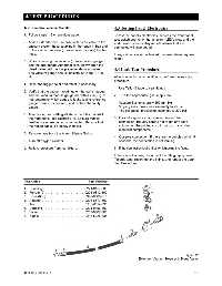
Description . . . . . . . . . . . . . . . . . . . . . . . . . . . . . Part Number
1. Coupling . . . . . . . . . . . . . . . . . . . . . . 0221-0157-300
2. Ferrule (2) . . . . . . . . . . . . . . . . . . . . . 0203-0812-300
3. Hose (6 ft.) . . . . . . . . . . . . . . . . . . . . 0995-6369-010
4. Adapter . . . . . . . . . . . . . . . . . . . . . . . 0204-8877-300
5. Tee . . . . . . . . . . . . . . . . . . . . . . . . . . 0213-6114-335
6. Coupling . . . . . . . . . . . . . . . . . . . . . . 0221-0156-300
7. Valve . . . . . . . . . . . . . . . . . . . . . . . . . 0207-6067-800
8. Nipple . . . . . . . . . . . . . . . . . . . . . . . . 0213-5025-335
Figure 19
Extender Vacuum Hose with Bleed Valve
0178-0135-000 Rev. A 4-5