
Page 504 - Med Plaza and Cancer Center
P. 504
4/TEST PROCEDURES
4.1 Testing the Switch Gauge Circuitry 7. Return each low contact assembly to its original
position (mark placed on transparent tape).
The following procedure can be used to check switch
gauge circuitry. See Figures 15 and 16. 8. Repeat steps 5 through 7 to test each high pressure
contact.
Tools Required:
#2 Phillips screwdriver 9. Replace the louvered panels.
1/16 hex wrench
Transparent tape Note: This test only checks switch gauge electronics; it
does not verify alarm set points.
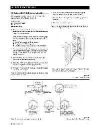
1. Remove the left and right louvered panels by
removing the Phillips head screws located on the top
of each panel. Figure 15.
2. Verify that the readings indicated on the switch gauge
and the associated line pressure gauge match to
within:
6 psig for the nominal 50 psi gases
18 psig for the 180 psi gases
2 inches mercury for the vacuum and evacuation
3. Place a suitable length of transparent tape across the
face of each switch gauge. The tape should be long
enough so that the ends of the tape clear the front
panel. Figure 16.
4. Mark the exact location of the contact assembly’s
brass pins on the transparent tape.
5. Using the 1/16 hex wrench, individually turn each low
contact so it just touches the gauge needle.
6. The alarm must sound on contact. If no alarm sounds
the panel needs repair. Note: Lip on louvered panel not shown. When replacing,
make sure lip is properly positioned.
Note: If remote alarms or monitors are connected, these
devices will be activated.
Figure 15
Louvered Panel Removal
Figure 16
Note: Shorting bar has been omitted for clarity. Testing the Switch Gauge Circuitry
0178-0135-000 Rev. A 4-1