
Page 500 - Med Plaza and Cancer Center
P. 500
3/THEORY OF OPERATION
3.3 Input Continuity 3.5 Outputs
The pressure switch inputs, J4 through J9, are also Figure 9
monitored for continuity.
Whenever an alarm condition is recorded by the
If, for example, the switch gauge connection at J4 should microprocessor, one of the 6 output ports will send a
become disconnected, the voltage on pin 25 of U3 will be Logic “1” signal to IC (Integrated Circuit) U1. IC-U1
pulled to ground (Logic “0”) through R20. The contains seven open collector Darlington drivers each
microprocessor will see this as a fault condition and capable of sinking 500 mA. Each driver energizes one of
initiate the alarm state. Disconnections at the other inputs six relays and LED bars. If more than one fault condition
(J5-J9) are monitored in the same fashion. is recorded by the microprocessor, additional signals are
passed to U1 which in turn energizes additional relays
Note: Unused switch gauge connections require the use and LED bars.
of a shorting harness to maintain the current path and
hold the respective U3 pin(s) at a Logic “1” level. In addition to buffer U1 the Logic “1” signal is also sent to
the base of Q1. This normally off transistor turns on and
causes the (-) terminal of the audio alarm to go to ground
3.4 Microcomputer potential. Since +12 volts is on the (+) terminal at all
times, the alarm activates the instant the (-) terminal
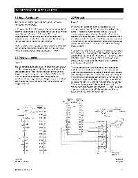
Figure 8 goes to ground potential.
The control/display board uses the 6805 microprocessor The microprocessor not only sends alarm signals for
(U3) for processing and controlling the functions of the audible and visual alarm activation, but it also sends,
area alarm panel. This microprocessor (,uP) is an 8-bit
under normal conditions, a Logic “1” signal to the normal
single chip microcomputer that contains 1100 bytes of lamp (DS3) and relay K1. The normal lamp and relay K1
ROM (Read Only Memory). This device uses 20 are energized if no alarms are present. When an alarm
input/output lines organized into 3 specific ports. Ports A condition is noted by U3, the Logic “1” signal to DS3 and
and B make up two 8-bit ports and Port C makes up a K1 goes to Logic “0”. Logic “0” deenergizes DS3 and K1.
single 4-bit Port.
This action takes place at the same time a Logic “1” is
sent to the audible alarm and specific LED bar. Thus, the
green normal lamp shuts off, the red abnormal lamp
glows and the audible alarm sounds.
Figure 8 Figure 9
Microprocessor Outputs
0178-0135-000 Rev. A 3-2