
Page 499 - Med Plaza and Cancer Center
P. 499
3/THEORY OF OPERATION
Note: Information in section 3 refers to models with code
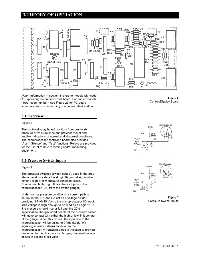
3 appearing on printed circuit board. For earlier models Figure 6
Control/Display Board
(lower code number), see Figure 29 for PC board
schematic and corresponding component identification.
3.1 Overview
Figure 6
The control/display board monitors from one to six
pressure or vacuum lines and provides visual and
audible indications of normal and abnormal conditions.
The microprocessor controlled board also provides
“Alarm Silence” and “Test” functions. Relays are provided
for the use of remote recording and/or monitoring
equipment.
3.2 Pressure Switch Inputs
Figure 7
The pressure switches (switch gauge), used in the area
alarm panel provide a low (Logic 0) ground signal when
either a high or low pressure condition exists.
Connectors J4 through J9 are the six inputs to the
microprocessor (U3) from the switch gauges.
Under normal pressure conditions, a current path is
set up so that RN and RA act as a voltage divider Figure 7
providing 3.7 +0.25 Vdc to the microprocessor U3 input. Pressure Switch Inputs
This voltage is high enough to be read as a Logic “1”. If
line pressure should rise or fall past the 20%
specification, the grounded needle of the pressure switch
will make contact with either the high or low limit contact
of the gauge. When this occurs, the input line to the
microprocessor will be pulled to 0 Vdc (Logic “0”),
signaling a failure (alarm) condition to the
microprocessor. A transzorb diode is included to provide
protection to the uP inputs by clamping transient voltage
spikes in excess of six volts.
3-1 0178-0135-000 Rev. A