
Page 494 - Med Plaza and Cancer Center
P. 494
2/DESCRIPTION
2.1 General Operation
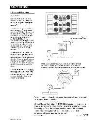
Figure 1 and 2
When all systems are operating
properly, the green NORMAL light
glows and the line pressure gauge
for each gas indicates actual line
pressure.
If a pressure change of more than
plus or minus 20% occurs (factory
setting), the NORMAL light goes out,
the audio alarm sounds and a red
ABNORMAL light is activated. The
audio signal continues until the Figure 1
ALARM SILENCE switch is Six Gas Area Alarm Panel
depressed; the indicator light, however,
remains on. When the system fault is
corrected, the indicator light goes
out, the alarm tone stops, and the
NOR MAL light is automatically
activated.
If there are two or more abnormal
alarms, the audio signal will sound
for each abnormality and the
appropriate ABNORMAL lights will be
activated. When the system faults are
corrected, the ABNORMAL indicator
lights go out. The alarm tone sounds
Switch Gauge Operation (NORMAL): The gauge pointer moves in
again if an abnormal condition still
exists. response to change in gas line pressure. Under normal pressure
conditions, the pointer will not be in contact with the gauge alarm contacts.
To test the area alarm panel circuitry for
proper operation, depress the TEST
switch. When depressed, all indicator
lights are activated, the audio alarm
sounds and a test of the internal
circuitry is performed.
Note: If break in line should occur the path will be interrupted
causing an alarm condition.
Switch Gauge Operation (ABNORMAL): As gas line pressure
goes to an abnormal (high or low) level, the pointer will move
accordingly. Once the pointer touches one of the contacts,
the normal (5V) signal will be interrupted and an alarm
condition will be sensed by the control
Figure 2
electronics. Area Alarm Circuit
0178-0135-000 Rev. A 2-1