
Page 497 - Med Plaza and Cancer Center
P. 497
2/DESCRIPTION
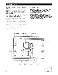
The following components are located in the rough-in 2.3 Remote Alarms
assembly:
Remote Alarm: A remote alarm panel is an audio-visual
Transformer: 120V primary (220V export), 14 volts alarm that is dependent on the area alarm panel. The
secondary. Note: The 120 VAC model is listed by conditions, as indicated by the area alarm, can be
Underwriters Laboratories. The 220 VAC unit has not duplicated by the remote alarm.
been investigated.
Remote Alarm Connector: Signal lights on the remote
Power Supply Board: Supplies regulated + 12VDC and + alarm panel receive their alarm trigger signal from the
5VDC to control/display board via connector. area alarm panel through the terminal strip located on the
control/display board. See Figure 13 for the wiring diagram
Audio Alarm: Produces audible alarm during alarm of the relays (remote alarm interface).
condition.
Connector-2 Pin: Audio alarm to power supply board
connection.
Connector-3 Pin: Transformer to power supply board
connection.
Hose Coupling(s): Quick connect style hose connection;
internal check valve design.
Figure 5
Rough-In Assembly
2-4 0178-0135-000 Rev. A