
Page 501 - Med Plaza and Cancer Center
P. 501
3/THEORY OF OPERATION
3.6 Spike Protection about 2.0 seconds and then low for about 2.0 seconds.
This low state resets the microprocessor at U3-28. When
IC-U1 (besides containing seven open collector U2-10 returns to a high state, the microprocessor begins
Darlington pairs) also contains seven reverse biased running its program.
diodes. The purpose of these diodes is to clamp the high
voltage spikes generated by the relay coils when they In order to prevent U2-10 from going low, which would
release. Additional input protection is provided by D1 cause the microprocessor to reset again, a retrigger input
through D8 (See Figure 28). is provided at U2-12. One of the microprocessors outputs
(U3-10) is capacitively coupled to this retrigger input
through C3. A low to high transition on U3-10 will
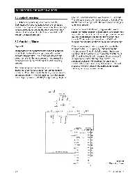
3.7 Watchdog Timer retrigger the oscillator so that the Q output remains high.
Figure 10 If the microprocessor fails to continually provide this
retrigger pulse, U2-10 goes low, thus resetting the
Incorporated on the control/display board is a special microprocessor. Should this fail to restart the program
circuit that monitors the microprocessor for proper execution, IC-U2 will continue to oscillate at both the Q
software program flow. This circuit also provides the (U2-10) and the Not Q (U2 11) outputs. Since transistor Q1
power-up reset to the microprocessor and resets the is capacitively coupled through C4 to U2-11, the
microprocessor in the event that it is not functioning continued oscillation will energize the audio alarm
properly. module with a short pulse every 4.5 seconds. This will
produce a “chirping” sound in the audio alarm module,
The main component of this circuit is IC U2. This indicating a microprocessor failure.
integrated circuit is set up as a free running astable
oscillator. C1 and R5 provide the timing components for
an output period of 4.6 ± 1.5 seconds (0.22 Hz square
wave). Upon power-up, U2-10 (Q output) will go high for
Figure 10
Watchdog Timer
3-3 0178-0135-000 Rev. A