
Page 505 - Med Plaza and Cancer Center
P. 505
4/TEST PROCEDURES
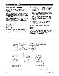
4.2 Setting Alarm Trigger Points 2. Place a suitable length of transparent tape across the
face of the switch gauge. The tape should be long
The alarm trigger points for each gas can be set on an enough so that the ends of the tape clear the front
individual basis by using either of the following panel. Figure 17.
procedures:
3. Mark a straight line on the tape between the desired
Note: The accuracy of this first “simplified” procedure is low pressure alarm setting on the scale and the pivot
limited. The second procedure which requires the use of (point) of the switch gauge needle.
a test apparatus is more accurate and is recommended
by BeaconMedæs. 4. Using the 1/16 hex wrench, individually turn the low
(left) contact to the desired set point by aligning the
Note: In accordance with NFPA Standard 56F (3-3), set center of the brass contact with the edge of the line
the alarms, “to indicate if the pressure in the piping on the tape.
system increases or decreases 20 percent from the
normal operating pressure”. 5. Repeat steps 3 through 4 to set the high (right)
pressure contact. Repeat this procedure for each
Procedure #1 additional gas module.
Tools required:
Phillips screwdriver 6. Remove tape and replace the louvered panel.
1/16 hex wrench
Transparent tape Procedure #2
Figure 18
1. Remove the left and right louvered panels by
removing the Phillips head screws located at the top The alarm trigger points for each gas (and vacuum) can
of each panel. Figure 15. be tested and set on an individual basis by using the
following procedure. This procedure requires a
special test apparatus as detailed.
Figure 17
Note: Shorting bar has been omitted for clarity. Alarm Trigger Adjustment (Procedure #1)
4-2 0178-0135-000 Rev. A