
Page 510 - Med Plaza and Cancer Center
P. 510
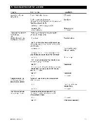
5/TROUBLESHOOTING GUIDE


              Symptom                  Test Procedure                            Repair/Replace

              Intermittent chirp from  Check if test button is stuck.            C/D board.
              audio alarm
                                       Confirm power supply operation.           See above.
                                       Check ,uP series number and use of jumper wire
                                       (See Note, Section 6.15).
                                       Substitute ,uP with known good unit:
                                       If operation OK -                         Microprocessor
                                       If chirp continues -                      C/D board.

              Continuous visual alarm  Remove louvered panel, check for pointer
              for single gas           contact with trigger point.
              OR
              Multiple alarms on one   If in contact -                           Readjust setting.
              or both sides of panel
                                       If not in contact, disconnect switch gauge, and
                                       alternately supply a short or open to connector
                                       on C/D board.
                                       If operation OK -                          Check switch gauge
                                                                                 wiring or replace.
                                       If operation not OK - check continuity between
                                       ground strap and rough-in box with ohmmeter.
                                       If not OK -                               Ground strap.
                                       If OK - check continuity between rough-in box
                                       and switch gauge metal case.
                                       If not OK -                                Repair open.
                                       If OK - remove front panel and check continuity
                                       through green wire at J2 and J3 from ground
                                       strap to C/D board.
                                       If not OK -                                Repair open.
                                       If OK -                                   C/D board.
              Remote indicator not     Remove J1 and check remote relay function
              functioning; panel OK    with ohmmeter.
              including test function
                                       If OK -                                    Check connector and
                                                                                 remote wiring.
                                       If not OK -                               C/D board.
              Alarm fails to activate   Disconnect switch gauge assembly; use
              during test procedure    ohmmeter to verify continuity to ground
                                       when contact is made.

                                       If OK -                                   C/D board.
                                       If not OK -                                Switch gauge assembly.


              0178-0135-000  Rev. A                                                                         5-2