
Page 511 - Med Plaza and Cancer Center
P. 511
6/REPAIR PROCEDURE
WARNING: After completing a repair of the alarm panel 3. While supporting the front panel, reach behind the
or any of its accessories, the test procedure (Section 4.3) lower part of panel and disconnect the electrical
must be performed to make sure that the alarm panel is in connector from the control/display board.
proper operating condition.
Note: If a remote alarm system is connected to the
WARNING: Electrical Shock Hazard. When interface connector, remove the interface terminal strip
performing service procedures with the power connected, during this procedure. An alarm will sound at the remote
extreme care must be taken to avoid direct or indirect panel; notify appropriate hospital personnel prior to and
contact with the primary electrical circuitry. after any service work.
WARNING: Before servicing the area alarm panel, notify 4. While supporting the front panel, disconnect each of
appropriate hospital personnel. Local and remote alarms the gas supply hoses. To disconnect the hoses, push
will be activated during service procedures. back the outer ring of the coupling and pull the hoses
straight out.
CAUTION: Electrostatic discharge through the printed
circuit boards will damage the components. Handle all circuit 5. Remove the panel from the rough-in box.
boards by their nonconductive edges and use anti-static
containers for transporting them. Before servicing the 6. To replace the panel, reverse the procedure.
equipment, ground yourself and the service tool to
discharge any accumulated static charge by properly
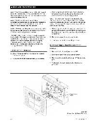
wearing a static control wrist strap. 6.2 Power Supply Board Replacement
Figure 20
6.1 Front Panel Removal
1. Remove the front panel (see Section 6.1).
1. Use a Phillips screwdriver to remove the 4 screws
from the front panel. 2. Disconnect each of the electrical connectors.
3. Pull the power supply board straight off the mounting
2. Pull out the front panel approximately 3 to 5 inches.
pins.
4. To replace the power supply board, reverse the
procedure.
Figure 20
Power Supply Board Removal
6-1 0178-0135-000 Rev. A