
Page 502 - Med Plaza and Cancer Center
P. 502
3/THEORY OF OPERATION
3.8 Ground Fault Detection
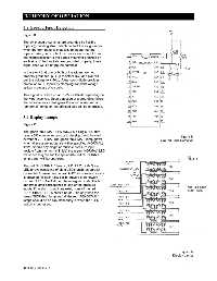
Figure 11
The six pressure switches are grounded by flexible
wipers (grounding strap) which contact the rough-in box
when the front panel is installed. To insure that the
wipers make good contact, two wires are brought from
the microprocessor to the gauge mounting brackets on
each side. If the brackets are grounded properly, these
signal lines will be at ground potential.
In the event that one or both of the wipers are not
properly grounded, pull-up resistors R32 and R31 will
pull the voltage to + 5Vdc. A transzorb diode provides
protection to uP inputs by clamping transient voltage
spikes in excess of six volts.
This signal is picked up at U3-27 or U3-26 depending on
the wiper involved. Upon detection of a grounding failure,
the microprocessor energizes the audio alarm and all
“abnormal” lamps on the affected side will be energized.
3.9 Display Lamps
Figure 12
The green “NORMAL” LED (DS3) is a single LED that
uses a 390 ohm series resistor to develop the dc forward Figure 11
current of 22 +4 mA. The green “NORMAL” lamp glows Ground Fault Detection
when all pressure inputs are within specified (NORMAL)
limits. Should any single or multiple pressure input
deviate from the normal limit(s) the green “NORMAL” LED
will be deenergized and the appropriate red “ABNORMAL”
lamp bar(s) will be energized.
The red “ABNORMAL” lamps (DS1, DS2, DS4-7) are
LED arrays consisting of eight LED’s each, as parallel-
connected four-element series. A 120 ohm series resistor
is provided for each LED bar to provide a dc forward
current of 28 ± 4 mA during the energized state. Each
abnormal lamp corresponds to one of the pressure
inputs. If no alarm conditions exist, none of the red
“ABNORMAL” LED’s should be on. The only time the
green “NORMAL” lamp and all the red “ABNORMAL”
lamps should be on simultaneously is when the “TEST”
switch is depressed.
Figure 12
Display Lamps
0178-0135-000 Rev. A 3-4