
Page 503 - Med Plaza and Cancer Center
P. 503
3/THEORY OF OPERATION
3.10 Relays
Figure 13
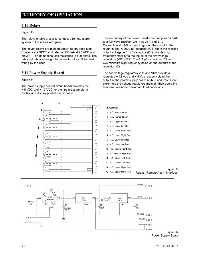
The relays enable a user to connect a remote alarm The secondary of the power transformer supplies 14 VAC
system to the area alarm panel. to a full wave rectifier (CR1) via J1-1 and J1-2.
Connection at J1-3 is used to ground the circuit to the
The seven relays are molded epoxy-dip dry-reed type. rough-in box. A 2000 ,uF capacitor (C4) filters the rectified
Contacts are SPDT and rated at 250 mA at 28 VDC and output voltage. A 0.1,uF capacitor (C1) provides high
30 VAC. The dc nominal coil resistance is 500 ohms. The frequency stability to the inputs of the two voltage
relay outputs are brought to connector block J1 for field regulators (VR1-VR2). The 2.2 ,uF capacitors (C2 and
wiring by the user. C3) minimize high frequency noise on the outputs of the
regulator IC’s.
3.11 Power Supply Board The two voltage regulators VR1 and VR2 provide a
regulated + 12 Vdc and + 5 Vdc respectively to the
Figure 14 output of the power supply board at J2-3 and J2-2. Heat
sinks help the voltage regulators maintain their operating
The power supply printed circuit board provides the
temperatures under maximum load conditions.
+ 5 VDC and + 12 VDC for the line pressure alarm
control and display printed circuit board.
Figure 13
Relays (Remote Alarm Interface)
Figure 14
Power Supply Board
3-5 0178-0135-000 Rev. A