
Page 495 - Med Plaza and Cancer Center
P. 495
DESCRIPTION
2.2 Components Circuit Test Button: When depressed, activates all
indicator lights, sounds audible alarm and tests the
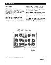
Figure 3, 4, and 5 internal circuitry.
The following list and figures indicate the major Line Pressure Gauge(s): Continuously indicates the actual
components of the area alarm panel. The six gas area line pressure for each specified gas.
alarm system, shown in this manual, uses components
that are similar to those used on smaller systems; i.e., Line Pressure Abnormal Light(s): Located in the bottom
one to five gas systems. section of each gas label is the ABNORMAL light. When
lit, this light indicates that the monitored gas line pressure
The following components are located on the front panel is beyond specified limits. Note: The ABNORMAL light
assembly: should stay lit, even when the alarm silence button is
depressed.
Normal Light (Green): When lit, indicates that the
pressure in all gas lines is within specified limits. Switch Gauge(s): Under normal pressure limits, this gauge
acts as a monitor for line pressure. If ABNORMAL line
Alarm Silence Button: When depressed, deactivates the pressure occurs, the gauge needle will contact either the
audible alarm. high or low limit contacts and activate the alarm.
Note: To gain access to switch gauges, remove the
louvered panels. Figure 3
Front Panel
6 0178-0135-000 Rev. A