
Page 77 - ansys
P. 77
Use a FLUENT fluid flow analysis system to apply a computational mesh to a geometry within
Workbench, then use FLUENT to define pertinent mathematical models (e.g., low-speed, high-speed,
laminar, turbulent, etc.), select materials, define boundary conditions, and specify solution controls
that best represent the problem to be solved. FLUENT solves the mathematical equations, and the
results of the simulation can be displayed in FLUENT or in CFD-Post for further analysis (e.g. contours,
vectors, etc.).
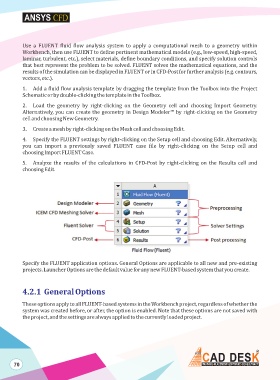
1. Add a fluid flow analysis template by dragging the template from the Toolbox into the Project
Schematic or by double-clicking the template in the Toolbox.
2. Load the geometry by right-clicking on the Geometry cell and choosing Import Geometry.
Alternatively, you can create the geometry in Design Modeler™ by right-clicking on the Geometry
cell and choosing New Geometry.
3. Create a mesh by right-clicking on the Mesh cell and choosing Edit.
4. Specify the FLUENT settings by right-clicking on the Setup cell and choosing Edit. Alternatively,
you can import a previously saved FLUENT case file by right-clicking on the Setup cell and
choosing Import FLUENT Case.
5. Analyze the results of the calculations in CFD-Post by right-clicking on the Results cell and
choosing Edit.
Specify the FLUENT application options. General Options are applicable to all new and pre-existing
projects. Launcher Options are the default value for any new FLUENT-based system that you create.
4.2.1 General Options
These options apply to all FLUENT-based systems in the Workbench project, regardless of whether the
system was created before, or after, the option is enabled. Note that these options are not saved with
the project, and the settings are always applied to the currently loaded project.
70