
Page 98 - Apprentice Manual_Neat
P. 98
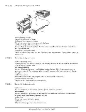
S5-Q124.)     The system in the figure below is what?


                       a.) Fuel pressure monitor
                       There is no fuel line in the figure.
                       b.) Exhaust gas temperature monitor
                       There is no exhaust stacks or components in the figure.
                       c.) *Electronic Speed Control system
                       Correct.  Note the magnetic pick-up, the wires to the controller and wires from the controller to
                       the actuator with arm.
                       d.) Generator frequency monitor
                       The figure contains an actuator with arm.  Monitors do not have actuators.  They only have sensors to
                       monitor with.

        S5-Q125.)      Device B in the figure above is:

                       a.) Photo proximity switch
                       A photo proximity switch would not work well in a dirty environment like an engine. It  must remain
                       clean so as to see the light beam.
                       b.) *Magnetic pick-up
                       Correct.  Magnetic pick-ups are used with ferrous metal gears.  When the gear tooth passes, it
                       generates a pulse.  It does not matter if it is covered in grease or oil, it uses magnetism to detect,
                       not optics.
                       c.) Pneumatic sensor
                       Pneumatic sensors are not fast enough to detect rotational speeds of an engine.
                       d.) Magnetic speed controller
                       There is no such device used in power generation.

        S5-Q126.)      Device A in the figure above is:


                       a.) Governor
                       It is one component of an electronic governor system, but not the governor.
                       b.) *Actuator
                       Correct.  This device is controlled by the controller and applies the appropriate force necessary
                       to correct errors detected by the magnetic pick-up.
                       c.) Regulator
                       It does not have any ability to regulate.
                       d.) Monitor
                       It has no sensing capability. It has an actuator arm.


                                          EGSA Apprentice Certification Program Study Guide - Page  90