
Page 60 - TEMPO COMMUNICATIONS Product Catalog_Distributors
P. 60
INSERTION LOSS MEASUREMENT
FIBER CATALOG
WHAT IS INSERTION LOSS?
An insertion loss (IL) measurement characterizes the light loss through a component or connection.
There are two accepted methods for measuring insertion loss, both of which may be found in reference document FOTP-171,
published by the Electronic Industry Association (EIA).
Insertion loss measurements require a light source, an optical power meter, and a patch cable manufactured to precise
tolerances, known as a reference cable.
In general, an insertion loss measurement is a two step process:
1) Establish a baseline power level measurement for the light source and reference cable in use. This is referred to as
“referencing” or “calibration.”
2) Connect the device under test and measure the difference between the measured power and the Reference power.
INSERTION LOSS MEASUREMENTS
To measure the insertion loss of a connector/cable, do the following:
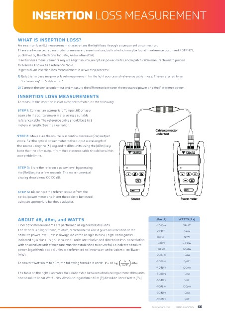
STEP 1: Connect an appropriate Tempo LED or laser
source to the optical power meter using a suitable
reference cable. The reference cable should be 2 to 3
meters in length. See the illustration.
STEP 2: Make sure the source is in continuous wave (CW) output
mode. Set the optical power meter to the output wavelength of
the source using the [λ ] key and to dBm units using the [dBm] key.
Note that the dBm output from the reference cable should be within
acceptable limits.
STEP 3: Store the reference power level by pressing
the [Rel] key for a few seconds. The main numerical
display should read 00.00 dB.
STEP 4: Disconnect the reference cable from the
optical power meter and insert the cable to be tested
using an appropriate bulkhead adapter.
ABOUT dB, dBm, and WATTS dBm (P) WATTS (Px)
Fiber optic measurements are performed using decibel (dB) units. +10dBm 10mW
The decibel is a logarithmic, relative, dimensionless unit it gives no indication of the +3dBm 2mW
absolute power level. Loss is always indicated using a minus (-) sign, and a gain is 0dBm 1mW
indicated by a plus (+) sign. Because dB units are relative and dimensionless, a correlation
with an absolute unit of measure must be established to be useful. To indicate absolute -3dBm 0.5mW
power, logarithmic decibel units are referenced to linear Watt units: 0dBm = 1 milliwatt -10dBm 100μW
(mW). -20dBm 10μW
-30dBm 1μW
To convert Watt units to dBm, the following formula is used:
-40dBm 100nW
The table on the right illustrates the relationship between absolute logarithmic dBm units -50dBm 10nW
and absolute linear Watt units: Absolute logarithmic dBm [P] Absolute linear Watts [Px]
-60dBm 1nW
-70dBm 100pW
-80dBm 10pW
-90dBm 1pW
TempoCom.com | 1.800.652.2155 60