
Page 182 - ISCIR_2017
P. 182
th
Seminar on Structural Repair and Retrofit Using FRP Technology, 7 October 2004 – EIT Building, Thailand
- Rehabilitation of Earthquake-Damaged and Seismic-Deficient Structures using FRP Technology
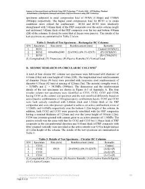
specimens subjected to axial compression load of 507kN (114kips) and 1780kN
(400kips) respectively. The higher axial compression load for RC03 is to create
conditions more critical for confinement. RC02 and RC03 were identically
strengthened with 3.42mm thick of the FRP composite over the entire column height
and additional 3.42mm thick of the FRP composite over the top and bottom 600mm
(2ft) of the columns. It should be noted that all layers were passive. The details of the
test specimens are summarized in Table-2 below.
Table-2: Details of Test Specimens – Rectangular RC Columns
S/N Specimen Size (mm) Reinforcement (mm) Remarks
1. RC01 Control+507kN(V)
2. RC02 610x406x2440 22-Ø19(L);Ø6.35-125(T) (P)+507kN(V)
3. RC03 (P)+1780kN(V)
(L)-Longitudinal; (T)-Transverse; (P)-Passive Retrofit; (V)-Vertical Load
4
D. SEISMIC RESEARCH ON CIRCULAR RC COLUMNS
A total of four circular RC column test specimens were fabricated with diameter of
610mm (24in) and clear height of 3.66m (12ft). The longitudinal steel reinforcements
of diameter 19mm (#6 bars) were provided with transverse steel reinforcements of
diameter 6.35mm (#2 bars) at spacing of 125mm (5in). The material strengths were f y
= 315MPa and f c’ = 34.5MPa (5000psi). The dimensions and the reinforcement
details of the test specimens are shown in Figure A-3 of Appendix A. The four
circular column test specimens were identified as CC01, CC02, CC03 and CC04,
having CC01 as the control test specimen and the rest retrofitted differently based on
active/passive combinations of fibreglass/epoxy confinement layers. CC02 and CC03
were both actively retrofitted with 2.44mm thick and 1.22mm thick of the FRP
composites and were also pressure-grouted to achieve an active confinement stress of
1.72MPa and 0.69MPa respectively over the bottom 1.22m height of the column. In
addition, both CC02 and CC03 were passively retrofitted with the FRP composites
having a nominal thickness of 3.25mm and over the lower height of 305mm (12in).
CC04 was pressure-grouted with cement grout to an active pressure of 1.38MPa. The
passive retrofit was the same with that for CC02 and CC03 but 1.38mm thick of FRP
composite in the circumferential direction and 0.61mm thick of FRP composite with
fibre oriented vertically were provided as the active retrofit over 0.91m height instead
of 1.22m height of the column. The details of the test specimens are summarized in
Table-3.
Table-3: Details of Test Specimens – Circular RC Columns
S/N Specimen Size (mm) Reinforcement (mm) Remarks
1. CC01 Control
2. CC02 Ø610 26-Ø19(L);Ø6.35-125(T) (A-E)+(P)
3. CC03 (A-E)+(P)
4. CC04 (A-C)+(P)
(L)-Longitudinal; (T)-Transverse; (P)-Passive Retrofit; (A-E)-Active Retrofit/Epoxy;
(A-C)-Active/Cement
oInnovative Seismic Strengthening System for Concrete Structuresp 180
© 2017 | T Imjai & R. Garcia (Eds.)
Page 4 of 23