
Page 37 - AAS & AES & FES 01082016_Neat
P. 37
the center of the plasma and is exposed to the high temperature of the plasma for several
milliseconds, longer than in other excitation sources; this contributes to the elimination of matrix
effects. Elements are atomized and excited simultaneously. The stability of the ICP discharge is
much better than arc or spark discharges, and precision of less than 1% RSD is easily achieved.
The dynamic range of an ICP source is approximately four to six orders of magnitude. It is often
possible to measure major, minor, and trace elements in a single dilution with an ICP source.
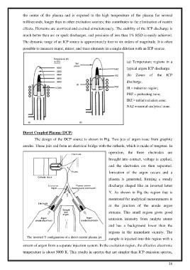
(a) Temperature regions in a
typical argon ICP discharge.
(b) Zones of the ICP
discharge.
IR = induction region;
PHZ = preheating zone;
IRZ = initial radiation zone;
NAZ = normal analytical zone.
Direct Coupled Plasma (DCP)
The design of the DCP source is shown in Fig. Two jets of argon issue from graphite
anodes. These join and form an electrical bridge with the cathode, which is made of tungsten. In
operation, the three electrodes are
brought into contact, voltage is applied,
and the electrodes are then separated.
Ionization of the argon occurs and a
plasma is generated, forming a steady
discharge shaped like an inverted letter
Y. As shown in Fig the region that is
monitored for analytical measurements is
at the junction of the anode argon
streams. This small region gives good
emission intensity from analyte atoms
and has a background lower than the
regions in the immediate vicinity. The
sample is injected into this region with a
stream of argon from a separate injection system. In the excitation region, the effective electronic
temperature is about 5000 K. This results in spectra that are simpler than ICP emission spectra,
36