
Page 966 - Chief Architect Reference Manual
P. 966
Chief Architect X10 Reference Manual
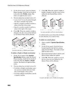
2. On the SIZING panel, under the Stretch 3. Click OK. When the symbol’s depth or
Planes heading, check the box beside 1 height is changed, only the cross section
to the left of the Width column. The defined by the Stretch Plane will be
field to its right becomes active. affected.
3. The new plane has an initial value of 0.
• Leave it at 0” to run the plane through
the object’s default origin point.
• Specify a negative number to define a
plane to the left of the origin.
• Specify a positive number to define a
plane to the right of the origin.
4. Click OK. When the symbol’s width is
changed, only the cross section defined Location and effect of Z-axis stretch planes
by the Stretch Plane will be affected. A symbol can have up to three Stretch Planes
in each direction, for a total of nine.
To define two stretch planes
1. Open a symbol’s Symbol Specification
dialog.
2. On the SIZING panel, check the boxes
beside 1 and 2 to the left of a column
under Stretch Planes. The fields to their
Location and effect of Width stretch planes
right becomes active.
To define a Depth or Height stretch plane 3. Specify the desired values to define each
1. On the SIZING panel of the Symbol Stretch Plane within the symbol.
Specification dialog, under the Stretch 4. Click OK. When the symbol is resized,
Planes heading, check the box beside 1 the two cross sections defined by the
to the left either the Depth or Height Stretch Plane will be affected.
column. The field to its right becomes
active.
2. The new plane has an initial value of 0.
• To define a Height stretch plane, spec-
ify a positive number between 0 and
the overall height of the symbol.
• To define a Depth stretch plane, specify
a negative number.
Location and effect of two Width stretch planes
966