
Page 88 - Airblade® Dryer - Mix and Match
P. 88
AIRBLADE® DRYER Mix and Match
Installation
10-Nozzle Frame Assembly: Wall Mounted
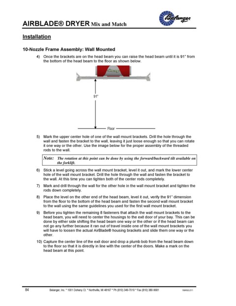
4) Once the brackets are on the head beam you can raise the head beam until it is 91” from
the bottom of the head beam to the floor as shown below.
91”
Floor
5) Mark the upper center hole of one of the wall mount brackets. Drill the hole through the
wall and fasten the bracket to the wall, leaving it just loose enough so that you can rotate
it one way or the other. Use the image below for the proper assembly of the threaded
rods to the wall.
Note: The rotation at this point can be done by using the forward/backward tilt available on
the forklift.
6) Stick a level going across the wall mount bracket, level it out, and mark the lower center
hole of the wall mount bracket. Drill the hole through the wall and fasten the bracket to
the wall. At this time you can tighten both of the center rods completely.
7) Mark and drill through the wall for the other hole in the wall mount bracket and tighten the
rods down completely.
8) Place the level on the other end of the head beam, level it out, verify the 91” dimension
from the floor to the bottom of the head beam and fasten the second wall mount bracket
to the wall using the same guidelines you used for the first wall mount bracket.
9) Before you tighten the remaining 8 fasteners that attach the wall mount brackets to the
head beam, you will need to center the housings to the exit door of your bay. This can be
done by either side shifting the head beam one way or the other or if the head beam can
not go any further because it ran out of travel inside one of the wall mount brackets you
will have to loosen the actual AirBlade® housing brackets and slide them one way or the
other.
10) Capture the center line of the exit door and drop a plumb bob from the head beam down
to the floor so that it is directly in line with the center of the doors. Make a mark on the
head beam at this point.
84 Belanger, Inc. * 1001 Doheny Ct. * Northville, MI 48167 * Ph (810) 349-7010 * Fax (810) 380-9681 1MANUL011