
Page 123 - DryLite® Dryers
P. 123
®
DRYLITE DRYER
Chapter 8: Maintenance
Motor Maintenance Supplied by Baldor®
Mounting Location (continued)
The motor must be securely installed to a rigid foundation or mounting surface to minimize
vibration and maintain alignment between the motor and shaft load. Failure to provide a
proper mounting surface may cause vibration, misalignment and bearing damage.
Foundation caps and sole plates are designed to act as spacers for the equipment they
support. If these devices are used, be sure that they are evenly supported by the
foundation or mounting surface.
When installation is complete and accurate alignment of the motor and load is
accomplished, the base should be grouted to the foundation to maintain this alignment.
The standard motor base is designed for horizontal or vertical mounting. Adjustable or
sliding rails are designed for horizontal mounting only. Consult your Baldor distributor or
authorized Baldor Service Center for further information
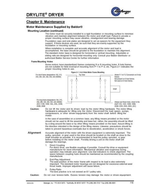
Frame Mounting Holes
Some motors have standardized frames containing 6 or 8 mounting holes. 6 hole frames
are not suitable for field reversal of mounting from F−1 to F−2, etc. Figure 2-1 indicates the
proper mounting holes to use.
Caution: Do not lift the motor and its driven load by the motor lifting hardware. The motor lifting
hardware is adequate for lifting only the motor. Disconnect the load (gears, pumps,
compressors, or other driven equipment) from the motor shaft before lifting the
motor.
In the case of assemblies on a common base, any lifting means provided on the motor
should not be used to lift the assembly and base but, rather, the assembly should be lifted
by a sling around the base or by other lifting means provided on the base. Assure lifting in
the direction intended in the design of the lifting means. Likewise, precautions should be
taken to prevent hazardous overloads due to deceleration, acceleration or shock forces.
Alignment Accurate alignment of the motor with the driven equipment is extremely important. The
pulley, sprocket, or gear used in the drive should be located on the shaft as close to the
shaft shoulder as possible. It is recommended to heat the pulley, sprocket, or gear
before installing on the motor shaft. Forcibly driving a unit on the motor shaft will
damage the bearings.
1. Direct Coupling
For direct drive, use flexible couplings if possible. Consult the drive or equipment
manufacturer for more information. Mechanical vibration and roughness during
operation may indicate poor alignment. Use dial indicators to check alignment. The
space between coupling hubs should be maintained as recommended by the coupling
manufacturer.
2. End-Play Adjustment
The axial position of the motor frame with respect to its load is also extremely
important. The standard motor bearings are not designed for excessive external axial
thrust loads. Improper adjustment will cause failure.
3. Pulley Ratio
The best practice is to not exceed an 8:1 pulley ratio.
Caution: Do not over tension belts. Excess tension may damage the motor or driven equipment.
1MANUL960 Belanger, Inc. * PO BOX 5470. * Northville, MI 48167-5470 * Ph (248) 349-7010 * Fax (248) 380-9681 119