
Page 12 - DuraJet™ / AlumaJet™ Arches
P. 12
DURAJET™ ARCH
Introduction
Overview
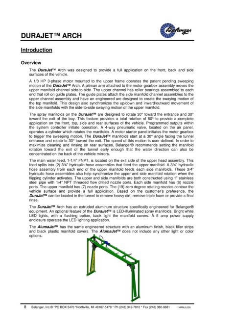
The DuraJet™ Arch was designed to provide a full application on the front, back and side
surfaces of the vehicle.
A 1/3 HP 3-phase motor mounted to the upper frame operates the patent pending sweeping
motion of the DuraJet™ Arch. A pitman arm attached to the motor gearbox assembly moves the
upper manifold channel side-to-side. The upper channel has roller bearings assembled to each
end that roll on guide plates. The guide plates attach the side manifold channel assemblies to the
upper channel assembly and have an engineered arc designed to create the swaying motion of
the top manifold. This design also synchronizes the up/down and inward/outward movement of
the side manifolds with the side-to-side swaying motion of the upper manifold.
The spray manifolds on the DuraJet™ are designed to rotate 30° toward the entrance and 30°
toward the exit of the bay. This feature provides a total rotation of 60° to provide a complete
application on the front, top, side and rear surfaces of the vehicle. Programmed outputs within
the system controller initiate operation. A 4-way pneumatic valve, located on the air panel,
operates a cylinder which rotates the manifolds. A motor starter panel initiates the motor gearbox
to trigger the sweeping motion. The DuraJet™ manifolds start at a 30° angle facing the tunnel
entrance and rotate to 30° toward the exit. The speed of this motion is user defined. In order to
maximize cleaning and rinsing on rear surfaces, Belanger® recommends setting the manifold
rotation toward the exit of the tunnel early enough that the water direction can also be
concentrated on the back of the vehicle mirrors.
The main water feed, 1-1/4” FNPT, is located on the exit side of the upper head assembly. This
feed splits into (2) 3/4” hydraulic hose assemblies that feed the upper manifold. A 3/4” hydraulic
hose assembly from each end of the upper manifold feeds each side manifolds. These 3/4”
hydraulic hose assemblies also help synchronize the upper and side manifold rotation when the
flipping cylinder activates. The upper and side manifolds are both constructed using 1” stainless
steel pipe with 1/4” NPT threaded flow drilled nozzle ports. Each side manifold has (6) nozzle
ports. The upper manifold has (7) nozzle ports. The (19) zero degree rotating nozzles contour the
vehicle surface and provide a full application. Based on the customer’s preference, the
DuraJet™ can be located in the tunnel to remove heavy dirt, remove triple foam or provide a final
rinse.
The DuraJet™ Arch has an extruded aluminum structure specifically engineered for Belanger®
equipment. An optional feature of the DuraJet™ is LED-illuminated spray manifolds. Bright white
LED lights, with a flashing option, back light the manifold covers. A 5 amp power supply
enclosure operates the LED lighting application.
The AlumaJet™ has the same engineered structure with an aluminum finish, black filler strips
and black plastic manifold covers. The AlumaJet™ does not include any other light or color
options.
8 Belanger, Inc.® *PO BOX 5470 *Northville, MI 48167-5470 * Ph (248) 349-7010 * Fax (248) 380-9681 1MANUL028