
Page 25 - stanochny park
P. 25
PROFESSIONAL ADVICE PROFESSIONAL ADVICE
the machine. Before filling new the uneven impregnation of rollers, and the circle should be
working fluid (oil), the tank the coolant circle, improper located symmetrically between
must be thoroughly cleaned installation - non-concentric them. The circle is imparted with
and washed with kerosene. installation of the circle, etc. a light impetus to a slow rotation.
Fig. 1. Setting the damping of
the extreme positions of the The frequency of replacement With an unbalanced circle, After the stop, the upper point
table. of the working fluid is once a centrifugal force arises that of its periphery is noted and the
a year. The brand of working causes vibration. With high-speed weight is moved into it along the
fluid is OT - CHP oil. Viscosity grinding, the danger of breaking groove.
20 - 25 / 50ºС. Hydraulic tank the wheel from cutting forces is This operation is repeated
capacity - 130 l. The Russian reduced, but the risk of breaking until the circle comes to an
analogue of branded oil is I by centrifugal force increases. indifferent balance, i.e. will stop in
20A oil. The wheel is balanced different positions.
Fig. 2. The operation is outside the grinding machine Then follows a second
Adjustment performed (as an option): the on balancing stands. The circle (test) balancing with a change
and control of
working fluid fitter and the operator-grinder mounted on the mandrel is in the direction of rotation of the
pressure of the machine. mounted on supports – cylindrical circle.
rollers or disks (Fig. 4).
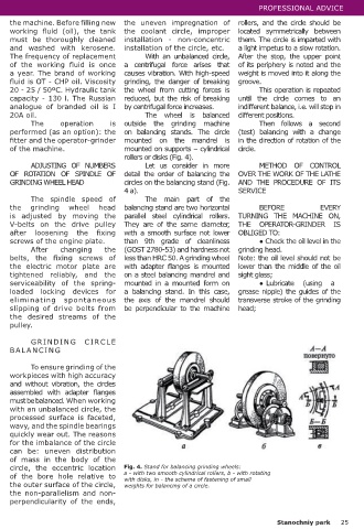
ADJUSTING OF NUMBERS Let us consider in more METHOD OF CONTROL
OF ROTATION OF SPINDLE OF detail the order of balancing the OVER THE WORK OF THE LATHE
Note: the hydraulic GRINDING WHEEL HEAD circles on the balancing stand (Fig. AND THE PROCEDURE OF ITS
circuit switch tap and pressure 4 a). SERVICE
gauge for monitoring the The spindle speed of The main part of the
pressure in them are located the grinding wheel head balancing stand are two horizontal BEFORE EVERY
on the right side wall of the is adjusted by moving the parallel steel cylindrical rollers. TURNING THE MACHINE ON,
control cabinet. V-belts on the drive pulley They are of the same diameter, THE OPERATOR-GRINDER IS
after loosening the fixing with a smooth surface not lower OBLIGED TO:
ADJUSTING OF THE TRANSVERSE screws of the engine plate. than 9th grade of cleanliness ● Check the oil level in the
EXTREME PROVISIONS OF THE After changing the (GOST 2780-53) and hardness not grinding head.
GRINDING WHEEL HEAD (Fig. 3) belts, the fixing screws of less than HRC 50. A grinding wheel Note: the oil level should not be
The value of the transverse extreme positions of the grinding wheel head is set using the the electric motor plate are with adapter flanges is mounted lower than the middle of the oil
disks 10 and 11. The disks are connected with the drums 12 and 13. The drum 12 sets the rear extreme tightened reliably, and the on a steel balancing mandrel and sight glass;
position of the grinding headstock, the drum 13 - the front one. serviceability of the spring- mounted in a mounted form on ● Lubricate (using a
Setup process: loaded locking devices for a balancing stand. In this case, grease nipple) the guides of the
● set the grinding head with the flywheel of the lateral feed in the front desired position eliminating spontaneous the axis of the mandrel should transverse stroke of the grinding
or in the rear; slipping of drive belts from be perpendicular to the machine head;
● loosen the locking screw 15 and rotate the corresponding drum so that the risk of the the desired streams of the
required lateral feed coincides with the notch on the fixed pointer; pulley.
● lock the position of the drums with screw 15.
GRINDING CIRCLE
Note: the locking screw 15 of the mechanism BALANCING
for adjusting the values of the transverse feeds is
located on the front panel of the machine under To ensure grinding of the
the handles (2 pcs.) For turning on the mechanical workpieces with high accuracy
longitudinal feed of the table and the lateral feed of and without vibration, the circles
the grinding head. assembled with adapter flanges
must be balanced. When working
CLEANING OF THE SUCTION BOX AND with an unbalanced circle, the
REPLACING OF THE OIL FILTER ITEM (Fig. 2) processed surface is faceted,
wavy, and the spindle bearings
To clean the hydraulic oil from dirt and quickly wear out. The reasons
impurities, a filter element of the YIPA 627-793- for the imbalance of the circle
330 brand is used (an analog of the proprietary can be: uneven distribution
filter element is the filter element of the OM 590 of mass in the body of the
automobile oil system, Poland). circle, the eccentric location Fig. 4. Stand for balancing grinding wheels:
The suction box 3 is cleaned and the oil filter of the bore hole relative to a - with two smooth cylindrical rollers, b - with rotating
element 4 is replaced by a qualified fitters. The the outer surface of the circle, with disks, in - the scheme of fastening of small
weights for balancing of a circle.
Fig. 3. Setting the mechanism of the value specified operation coincides with the operation of the non-parallelism and non-
of the transverse feeds. replacing the working fluid in the hydraulic system of perpendicularity of the ends,
24 Stanochniy park Stanochniy park 25